Shield DDS Board AD9910 v2.0
Schemes, BOMs, Layouts, 2D and 3D Renders, 3D Models, Charts, Instructions, References…
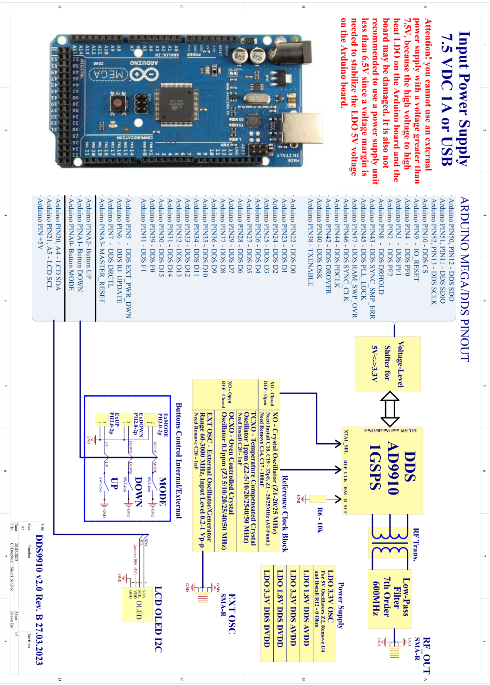
Shield DDS Board AD9910 v2.0 Connection Diagram (rev.B)
Download:
DDS AD9910 Shield Board v2.0 Connection Diagram (rev.B) (90 downloads)
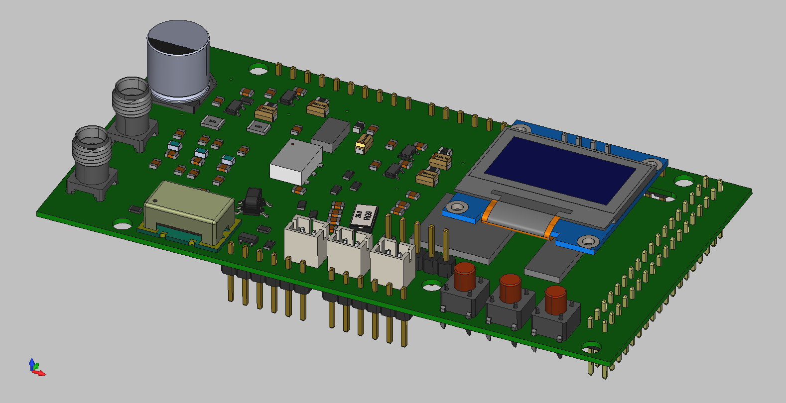
Shield DDS Board AD9910 v2.0 with OLED 3D Model top front overview
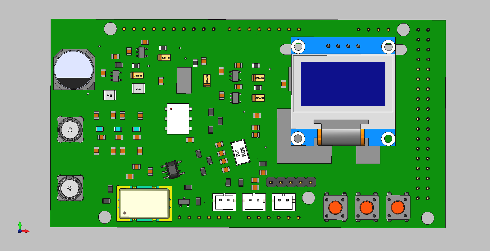
Shield DDS Board AD9910 v2.0 with OLED 3D Model top front view
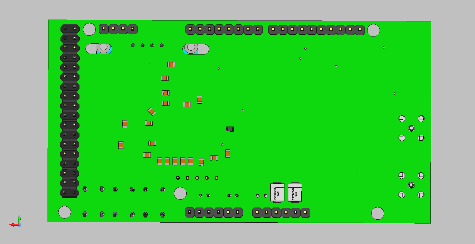
Shield DDS Board AD9910 v2.0 with OLED 3D Model bottom view
Download:
3D Model Shield AD9910 v(2.0) with OLED (NMV) (180 downloads)
Operating Instruction for DDS AD9910 v2.0 Shield Board (rev.A) with Connection Diagram (rev.B)

DDS AD9910 Shield Board v2.0 Operating Instruction (rev.A) with Connection Diagram (rev.B) [title]
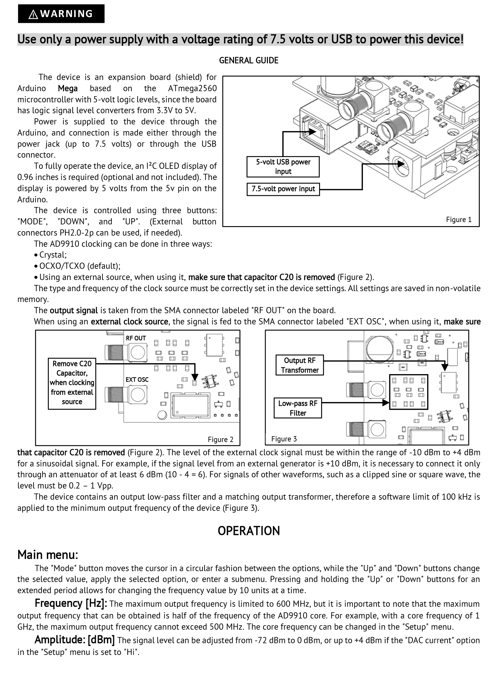
DDS AD9910 Shield Board v2.0 Operating Instruction (rev.A) with Connection Diagram (rev.B) [page 1]
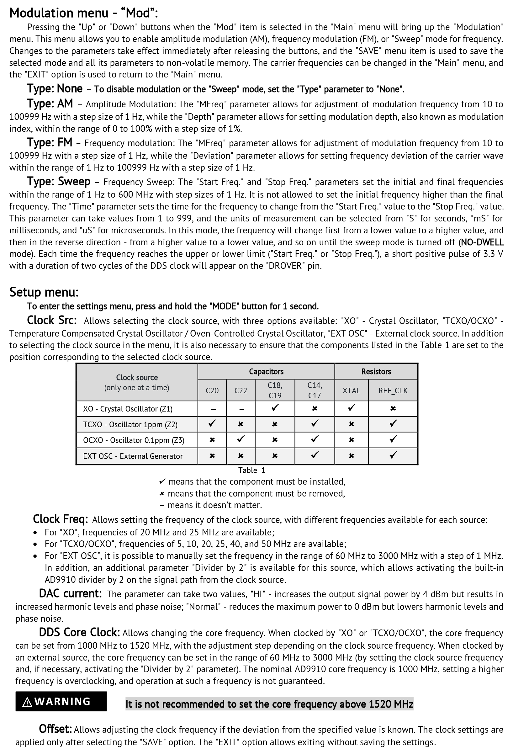
DDS AD9910 Shield Board v2.0 Operating Instruction (rev.A) with Connection Diagram (rev.B) [page 2]
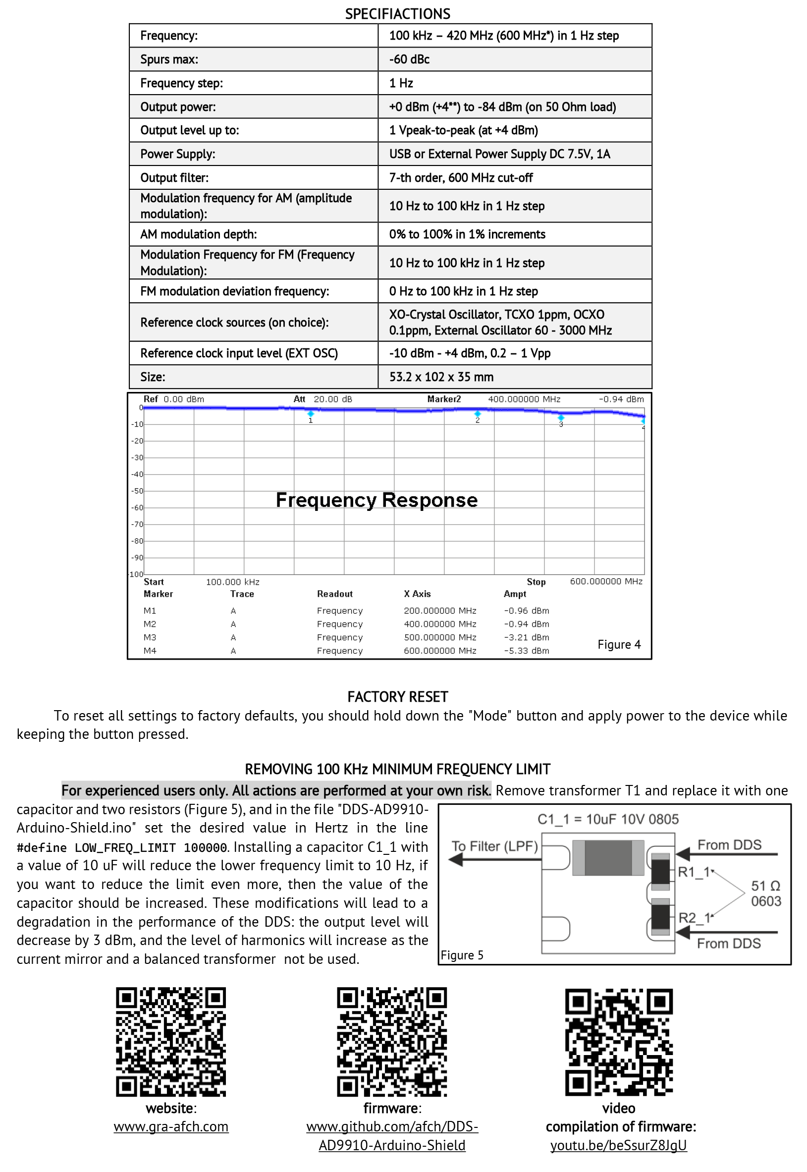
DDS AD9910 Shield Board v2.0 Operating Instruction (rev.A) with Connection Diagram (rev.B) [page 3]

DDS AD9910 Shield Board v2.0 Operating Instruction (rev.A) with Connection Diagram (rev.B) [connection diagram]
Only Operating Instruction:
DDS AD9910 Shield Board v2.0 Operating Instruction (rev.A) (84 downloads)
Only Connection Diagram:
DDS AD9910 Shield Board v2.0 Connection Diagram (rev.B) (90 downloads)
List of modifications, additions, identified errors and their corrections…
08 November 2024
Issue:
If you write through the USB port to DDS9910 Shield Board spurs may occur with a level of approximately -80 dBm multiplied by 48 MHz, such as 48.96, 144 MHz, etc.
This is due to the operation of the USB-UART Controller on the Board.
Arduino Mega 2560 R3 Board with CH340C Controller operates at a frequency of 12×4 = 48 MHz for example.
Solution:
The solution to this problem is to power the Arduino Mega through an external 7.5V Power Supply.
In this case there are no additional spurs occurs since the USB-UART controller does not involved.
Note:
We offer external Power Supplies for our DDS RF Units and they are suitable for Shield Boards perfectly:
Power Supply for DDS and RF Units [7.5V/2A] [AC Pug] (US, EU, UK) Low Noise
07 November 2024
Modification:
Capacitor C12 replaced for 100uF X5R 6.3V 0805
Result:
TCXO at 40MHz works better on phase noise level then TCXO at 50MHz
31 May 2024
Issue:
An error has been identified in products manufactured before May 2024, which may lead to an increase in phase noise.
Solution:
The following components needs to be replaced for TCXO 40/50MHZ:
- R37 – 680R 0805;
- C13 – 470pF NP0 0805;
- C15 – 100pF NP0 0805;
- C12, C23, C24, C26, C28, C30, C39, C37, C45, C47, C56, C58, C66 – 1uF 10V X7R 0805.
Replacing these components will significantly reduce phase noise.
Free Correction Service:
If you are unable to perform these modifications by yourself you can send the DDS AD9910 v2.0 Shield Board to us.
We will carry out all the necessary work free of charge and you will only need to cover the shipping costs.
PCB Design Schematics Case and Software made by GRA & AFCH

