
How to drive a Nixie Tubes
How to drive a Nixie Tube
If you want to build a Nixie display or a Nixie Clock you’ll have to know how to use and drive Nixie Tubes. We will discuss here basic and multiplexed use of the Tubes. There are a number of schematics to illustrate various usages.
How it works
A Nixie Tube is a gas discharge device. Their colour and operating voltage are determined by the properties of the neon gas within. Tubes ignite at 140-170 V, slightly varying by type. Once ignited, their resistance is very low so a series of resistors is necessary to limit the current, typically to 1-5 mA. The operational voltage of the Tube is 90-130 V depending on type. If the voltage drops below the turn-off voltage, the Nixie will go out. For a ZM1000, for example, the turn-off voltage is specified at 118 V at room temperature, but practice shows that japanese Nixies still work at 100 V.Because of Supply voltages of 170-300 V are used some people think they need switching devices that can handle these High voltages. In practice, however, there are two circumstances that reduce the voltage you have to switch:
- First is that the voltage across the switch only rises to the Supply voltage minus the turn-off voltage of the Tube. When it drops below this, the Tube will become an isolator.
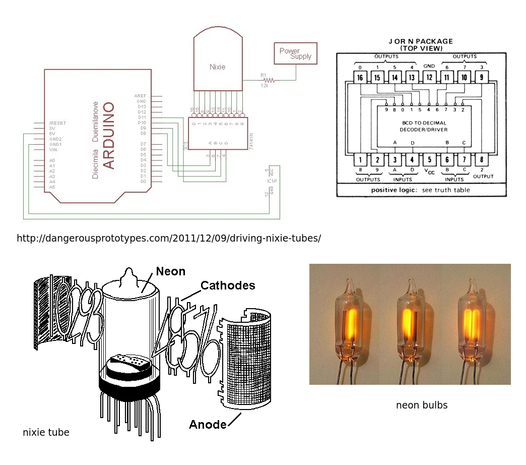
- Second, when there is one of the cathodes switched on, the anode voltage will be significantly lower than the Supply voltage. So if your driver circuit always turns the next cathode on before switching off the previous one, your cathode voltages will stay below 65 volts no matter what your Supply voltage is. You could connect a zener diode to one of the cathodes to prevent a situation where all cathodes are off. The once-popular SN74141 decoder – Nixie driver had built-in zener diodes of 55 volts on all outputs that could handle 1 mA. It’s predecessor, the 7441, did not have these, so you would have to take care to keep it’s output voltage under 70 V under all circumstances.
Basic cathode driver circuits
The 7441 and its successor, the 74141 were very common Nixie driver IC’s from the TTL era. If you can find a few 7441’s or 74141’s, you can use these vintage IC’s in your project. But they are hard to get and being TTL devices, they use more power and have larger input currents than modern IC’s. Many older MOS IC’s are not able to drive TTL inputs. In those cases, you will need a buffer to drive your 74141! So what are the other options:
- Use high-voltage transistors after a CMOS BCD-to-decimal decoder. As mentioned above, an Uceo rating of 70V is sufficient if you keep the Supply voltage below 200V or clamp all cathodes to some clamping voltage of 60V. You could try and connect only one cathode to a zener diode of 45V, so this cathode will light if no other is switched on, but you would probably need to use a 120 V transistor. Anyway, 250V transistors like BF422 or MPSA42 are quite affordable (~ € 0,45), so you can decide to just use these.

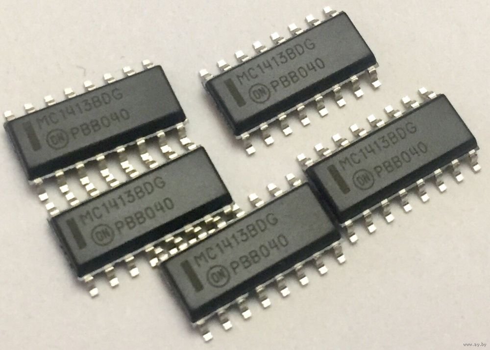
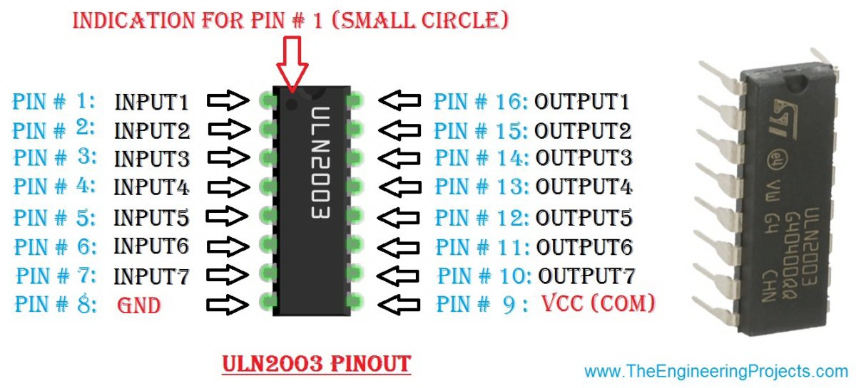
- Use high-voltage driving ICs. For example SN75468, it works fine. It contains 7 darlington transistors intended to switch inductive loads up to 500 mA and has a maximum output voltage of 100 V. Unfortunately, it has been declared obsolete by TI and it is becoming rare. The ULN2003 is pin-compatible with the 75468 but it can only handle 50V. You will have to protect it by connecting its pin 9 to a clamping voltage of 45 V. It shows good results with a zener diode of 44 V connected to pin 9.
- Use other more “modern” gas discharge Tube driver circuits, intended for flat-panel plasma displays such as Burroughs Panaplex displays. TI and National sold a number of these in the 70’s, but they are even more hard to find than the 74141. Plasma display driver circuits intended for flat-screen computer displays tend to have a large number of outputs and very compact packages.
- Finally, according to an old TI TTL Data Book, once upon a time there was the SN74142. It is said to contain a decimal counter, a 4-bit latch and a decimal decoder and Nixie driver. In 1976, this must have been a great IC, saving 2 packages per digit in a TTL frequency counter or voltmeter. Unfortunately.
Multiplexing Nixie Tubes
In a multiplexed display, all the corresponding cathodes of the Nixies are connected together in a bus structure. The anodes of the Nixies are switched on one by one and the right cathode is activated for every digit. If you do this fast enough, you get the illusion that all digits are on simultaneously.
The advantage of multiplexing is that you need fewer decoders and less wiring.
Multiplexing is nothing new. Multiplexed LED displays are used on alarm clocks, digital room thermostats, digital voltmeters, etc. A lot of voltmeter chips, calculator chips, alarm clock chips etc. already have multiplexed outputs to save IC pins. If you use a microcontroller such as a PIC for your project, you’ll have to program a display multiplexing routine.
So how do you multiplex Nixie Tubes? Isn’t that complicated and expensive?
To multiplex Nixies, you need to include anode driver circuits in design. These turn on and off the anodes of the Nixies. The anode drivers “float” at the Supply voltage of 170-250 V, and they are driven by the main circuit (your Clock, Meter, Calculator) that is at ground potential. In order to bridge this voltage gap, either a high-voltage transistor or a capacitor is used. Depending on the technology used in the main circuit, the anode drivers are driven with a 2-5 voltage swing from TTL or CMOS powered by 5 V, or maybe 24 V for older PMOS or NMOS circuits.
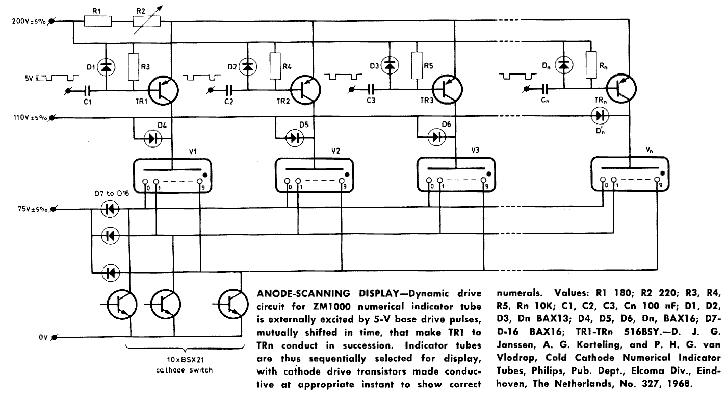
Many examples of multiplexed circuits for Nixies can be found on the web. For example, an anode-scanning display by Philips Elcoma which even has a dimming control, was in a bulk post on the sci.electronics.schematics news group. In the Game Archive web site, which contains a lot of information for pinball machine and video game colectors can be found a schematic of aBally 7-digit pinball machine display that uses 7-segment flat-panel neon displays. National used to have some anode driver circuits for Panaplex® displays, like the DM8880, but they are in short supply today.
Nixie Clock: the Driver
Calculating current limiting resistor. Every Nixie Tube is characterized by two voltage values:
- ignition voltage (Vign)
- maintaining voltage (Vm)
and by one or more current values:
- average/peak numeral current (Ik)
- average/peak decimal point current (Ikdp)
These values can be found in Nixie’s datasheets:

The typical schematic for connecting the Tube is following:

And the formula for calculating resistor R value is this:

And the power dissipated on the Tube is this:
![]()
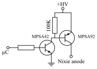
Discrete transistor driver
You can’t directly drive a Nixie Tube with microcontroller’s output pins: each Nixie cathode not connected to ground is at a voltage near to Vm.
The simplest solution is to use a transistor and connect its base to a microcontroller pin.
Not every transistor is able to sustain the high collector-base voltage (Vcbo): the most widely used one is MPSA42, which, as can be read on its datasheet – sustains a Vcbo of 300V.
The schematic for that drive is very simple:

The disadvantage of this approach is that you need a transistor for each cathode, so if your Nixie clock project uses 4 Nixies you need about 40 transistors!
Integrated circuit driver
In the past some integrated circuits were produced to drive Nixie Tubes; the most widespread ones, as was already mentioned, are 7441, 74141 and their russian “clones” K155ID1, KM155ID1, these can easily found on the web, for example on eBay. These ICs are called bcd-to-decimal decoder to drive Nixie Tubes and have 4 input pins (A/B/C/D) and 10 output ones (0..9).
Their function is very simple: if you send to input pins a number (0 to 9) in binary form, the corresponding output pin is set high. All the input-output states are listed as a “truth-table” in the datasheet:

Gra & Afch Nixie Clocks
We here at Gra & Afch offer a variety of parts for Nixie Clocks.
As well as Ready-to-Use assembled Clocks, Cases and DIY KITs that are presented in a separate sections in our shop.
And you can come visit it and look for yourself anytime: Spare parts, Nixie Tubes, Nixie Clocks without Cases, Nixie Clocks in Cases, DIY KITs for Nixie Clocks, Cases for Nixie Clocks.