
How to build your first Nixie Clock

![]()


Have you ever felt that LEDs are a little ‘cold’ or ‘plasticky’?
Do you yearn for that warm, comforting glow that only ionized gas behind glass can provide?
Do you have some Nixie Tubes gathering dust in your junk box or in long-forgotten test equipment?
Well, now you can bring them back to life!
Building a Nixie Tubes Digital Clock


Warning! As the design described in this article uses a transformerless power supply the whole circuit is at mains potential. Always disconnect it before making any adjustments etc. If you need to use an oscilloscope or other grounded instrument for debugging, the circuit MUST be operated through an isolating transformer. The finished design MUST be enclosed in a suitably insulated case and if push buttons are used instead of reed switches for time setting they must have mains rated insulation!
Information in this article is provided ‘as is’. All interested should only attempt to build this design if they are competent at electronics assembly and understand the dangers of mains voltages. No responsibility is accepted for any damage or injury (however it can be serious) or even disruption of the space-time continuum caused by anything remotely connected to this website 🙂
Introduction
A working simple example of professional double-sided PCB design is available for a similar to this assembly, it can be seen here. If the idea of building your own PCB really scares you, check Logic Applied, Neontime, Sphere, Cosmodog, wps, Cathode Corner, Dodocus, Karlsson, mapsevoli, nixieclock.net for ready-made ones or for KITs. An example of Gra-Afch Nixie Clock you can look for here.
Please refer to electricstuff.co.uk for any resources, mentioned in this article if needed.
So, have you built a Nixie clock before? If yes, you can share your design with us. More info on building Nixie Clocks can be found on our other articles. Also you can look for an Online Nixie Clock. Nixie Tube & driver sources and data can also be seen on the web. Nixie Clock emulator for Windows is another one interesting, Nixie Clock article in IEEE Spectrum magazine. A Nixie Tube cable TV box. All-Valve Nixie Clock. All these materials on Nixie Clocks can be in some way useful.
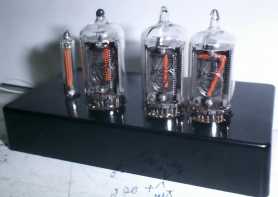
The design described below uses no exotic or obsolete components other than the Nixie Tubes themselves. It is made to be very compact and does not use a mains transformer, allowing it to be built into a nice small Case. It’s designed for 230v (220-240V) mains operation, but can be modified for 115v (110-120V), and can be configured for 50 or 60Hz Supplies.
Components cost should be well under UK ?10/US 15$ (excluding the Nixies). If it costs you much more, you’re shopping in the wrong places 🙂
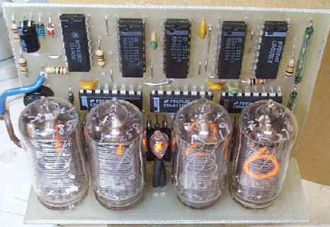
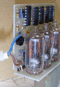
Also the artwork for a PCB design can be downloaded, which can be built either ‘flat’ (above centre image), or cut in two and ‘folded’ (above right) to make a very compact unit. An additional version of it is available which comprises 2 stacked boards under the Tubes (see pictures at the bottom of the article).
To avoid the need for unsightly buttons on the Case (and the need to isolate the mains voltage from the user), reed switches can be used for the time-setting function, these being operated by holding a magnet against the Case near the appropriate switch.
Circuit description
If you really don’t care how it works you can skip this section, but please don’t, as you may learn something useful…
The circuit uses CMOS 4017 counters to divide the 50Hz (or 60Hz) mains frequency down to 1Hz, and also to generate the 1-of-10 drive signals to drive the Tubes. The high-voltage driver stages use readily available low-cost MPSA42 transistors. IC drivers (like the TTL 74141) were not used for reasons of cost, availability and power consumption.
The 230V mains supply is rectified to produce an unsmoothed +340V peak-to-peak supply for the Nixie Tubes. Smoothing is not required as the 100Hz flicker will not be visible, it reduces the average power dissipation in the anode resistors R5-8 and avoids the need for a physically large capacitor. For 115V operation a voltage-doubler is required, producing a fairly smooth +250 VDC supply. The low-voltage supply for the CMOS ICs is derived from a resistor/zener dropper R1/2 and D1 (2 resistors are used to avoid exceeding the resistors’ voltage rating). One or two NE-2H neon bulbs provide a flashing dot or column indicator. You can alternatively use the decimal point of the ‘hours’ Nixie, but you will probably need to connect it via R3 to match the digit brightness, and you may in time find out that the brightness of the ‘hours’ digit fluctuates slightly as the dot switches on and off.
The 50Hz signal is current-limited by R11/12, and buffered by U8B, which is just being used as a buffer stage to buffer the high-impedance 50/60Hz signal for use by the fast-set switch. U8B’s CMOS input static-protection diodes clamp the voltage to the supply rails. C5 filters out fast mains transients and noise. C2/R10 and D5 reset the hours count to ‘1’ when it reaches ’13’. R9 allows the ‘minutes’ clock signal to be overridden by the time set buttons. R13 and C6 form a low-pass filter to reduce the effect of switch-bounce on the slow-set switch.
Note the different connection of the ‘hours’ Tube to U1, as ‘hours’ count from 1 to 12, whereas the minutes count from 0 to 59.
As the circuit is not isolated from the mains, it is ESSENTIAL to use an isolating transformer if you need to connect an instrument such as an oscilloscope. As the circuit draws only a small current, you can easily make a suitable isolating transformer using two identical (i.e. same secondary voltage) small low-voltage mains transformers with the secondaries connected together. When connected via an isolating transformer you can earth the 0V signal ground line.
Remember that there will still be dangerous voltages on the board!!!
PCB design
Information provided here is to allow you to make your own PCB for this assembly. The design can be built as a single PCB or the Tube section can be separated to make a compact unit with the electronics vertically mounted behind the Tubes. The main part of the board can also be separated and hard-wired to the Tubes with different pinouts to the ones used here.
The display part of the PCB is designed for the Tubes that were available, which are fairly standard size ‘generic’ ones with no maker’s name. Experimentally were found that ITT GNP-17A and Hivac XN11 Tubes have the same pinouts as the ones used in this design. The Tubes have 12 pins (0-9, point and anode). Some Nixies have 13 pins – the extra electrode is a ‘primer’, used to maintain ionisation to avoid flicker on multiplexed displays. This electrode is not necessary in the application described in this article and can be left unconnected. The PCB component layout drawing has the pinouts of the Tubes that were used are marked. The leads of wire-ended Tubes with different pinouts can usually be pre-formed to fit the PCB, but you won’t be able to seat the Tube hard against the PCB. For Tubes with solid pins, you’ll probably need to either make up your own display PCB section or hardwire them with or without sockets.
The PCB we will use is a single-sided and designed to be very compact and therefore has a rather high track density so it needs to be made very carefully. You can look for lots of info on making good-quality homebrew PCBs on the web.
Parts list e. g. BOM
Parts marked as * are for 115V doubler version only, parts marked as + are for 230V version (or 115V via transformer).
| Qty | Ref | Description | Typical mail-order price each, UK Pounds (multiply by approx 1.5 for US $) |
| 7 | U1-7 | 4017 (MC14017, CD4017, HEF4017 etc.) | 0.5-0.8 |
| 1 | U8 | 4013 (MC14013, CD4013, HEF4013 etc.) | 0.3-0.5 |
| 1 | D1 | 4V7 (=4.7 volt) 400 mW Zener diode | 0.05-0.1 |
| 2 | D2*, D3* | 1N4005, 6 or 7 diode | 0.05-0.1 |
| 1 | D4+ | W04, 5, 6 or 7 bridge rectifier (1 Amp, 400V or more) | 0.3-0.5 |
| 1 | D5 | 1N4148 or 1N914 signal diode | 0.02-0.05 |
| 1 | C1 | 100 uF 10V electrolytic capacitor, radial pins | 0.05-0.1 |
| 3 | C2, 5, 6 | 1 nF ceramic capacitor, 0.1″ pin spacing NB C2 may not be required – fit only if hours don’t roll over correctly (see notes) |
0.02-0.08 |
| 2 | C3*, C4* | 2.2 uF 350 VDC electrolytic or polyester/polyprop. capacitor. (not 250V as on she.). | 0.3-0.6 |
| 3 | C7-9 | 100 nF ceramic capacitor, 0.2″ pin spacing | 0.02-0.08 |
| 3 | R1, 2, 9 | 100K 0.125 or 0.25 watt resistor, 5% | 0.01-0.02 |
| 2 | R3, 4 | Resistor to suit Column neon Bulbs, around 680K 1/4W see below | 0.01-0.02 |
| 4 | R5-8 | Resistor to suit Nixies, around 47K, see below | 0.01-0.02 |
| 2 | R10, 13 | 10K 0.125 or 0.25 watt resistor, 5% | 0.01-0.02 |
| 2/3 | R11, 12, R14* | 1M 0.25 watt resistor, 5% | 0.01-0.02 |
| 1 | R15* | 220R 0.25 watt resistor, preferably fusible (flameproof) type 5% | 0.05-0.1 |
| 1 | R16+ | 1K 0.25 watt resistor, preferably fusible (flameproof) type 5% | 0.05-0.1 |
| 28 | R17-44 | 33K 0.1 or 0.125W sub-miniature resistor 5% | 0.01-0.02 |
| 28 | Q1-28 | MPSA42 transistor (300V Vceo, TO-92) | 0.05-0.15 |
| 4 | V1-4 | Nixie tubes | ———- |
| 2 | LP1, 2 | NE-2H or similar neon Bulb | 0.2-0.3 |
Assembly notes
If you intend to build the PCB as a ‘vertical’ version, it is suggested that you build and test it as a single PCB, for ease of access to components, then cut the board into two parts when you’ve got it working.
The PCB has a high track/component density and needs careful soldering with a fine tip. Check carefully for shorts, ESPECIALLY from the high-voltage anode supply (junction of R5-8), as a short from this line could cause severe damage or fire!
There are several wire jumper links on the PCB. these are made with tinned-copper wire (or component lead off cuts). If using a reel of TC wire, you can get nice straight links by stretching the wire slightly – this is easy to do if you unroll a foot or so, and pull it tight with pliers, then cut to short lengths. Take care when bending the leads of the reed switches – it is very easy to crack the glass. Use fine-nosed pliers to hold the lead between the glass and the bend.
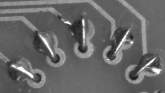
If you mount the Nixies close up against the PCB, do not solder the leads at the point where they come through the PCB, as this can cause mechanical stress and cracking. Instead, fold the wires over and solder to the larger outer pads, as shown below.
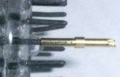
Many Nixies have short, solid pins instead of wires – do not attempt to solder directly to this type of Tube pin, as you run a high risk of cracking the glass. To connect to Tubes like this, the socket contacts from a dismantled a ‘D’ type socket (the type with turned pins, not the cheap stamped-pin ones) provide an easy method. You could either just hardwire to the pins, make a PCB to hold them, or epoxy them into holes drilled into a plastic or fibreglass sheet to make a proper socket.
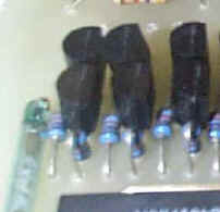
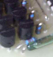
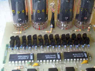
The driver area is very densely packed – use subminiature (1/8 watt) 33K resistors if possible. See the close-ups (below). If you use larger 1/4 watt resistors, you may need to space the transistors off the PCB slightly.
It may be necessary to experiment with the value of the anode resistors R5-8, so don’t solder them all in – just tack R8 in place and check that the Tube brightness is acceptable. If you see any significant purple ‘haze’ in the Tube, or parts of the Tube other than the digits lighting, the current is too high, and you should increase the resistor value. Avoid the temptation to run the Tubes too brightly, as this will make the glass blacken and reduce their life considerably. Check for Tube blackening after running the Clock for a few months. Recommended values to start with : 47K (R5-8), 680K (R3,4). For the 115V voltage-doubler version, these will probably need to be increased. If you are planing to use larger Tubes, you will probably need to decrease R5-8, and possibly use higher wattage versions (1 watt) to cope with the extra power dissipation.
If you have found suitable values for specific Tubes and Power Supplies, please share.
The 4017 counters can power up in ‘strange’ count states. This means that on power-up, the Clock may show an invalid time or even multiple digits lit in one Tube. Use the ‘Fast Set’ mode to increment the display until it is sensible. The counters in the divider network may also assume odd states so the first ‘minute’ after power up could be either short or long! For optimum accuracy wait until the minute display changes before setting the time.
One builder has reported a problem with the hours not resetting properly, i.e. going 9, 10, 11, 12, 3, 4, 5. This could be due to timing differences between the makes of 4017 and 4013 used for U1 and U8. This was fixed by adding a 220 pF capacitor between pins 15 and 16 of U1. If you encounter this problem you may find that a smaller value could be required, e.g. 100 pF. Another one reported the hours count going 9, 10, 11, 12, 1, 2, 1, 2 which was fixed by removing C2.
Thanks to Steven Rougier for this alternative fix for this issue : Disconnect pin 15 of U1 from the rest of the circuit and connect it to pin 5 of U8A via a 1n capacitor. Also, connect pin 15 of U1 to ground via a 10k resistor. C2 and the 220 pF are not required. The Clock will then always roll over correctly since U1 will reset U8B and U8B will then reset U1, in sequence rather than in parallel. With the parallel situation, the first i.c. to reset removes the reset signal from the other and unreliable results can occur.
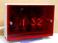
Making a simple Case for the Clock
A nice and easy way to make a simple Case for the Clock is to get a standard plastic project box of an appropriate size and replace the lid with a piece of light-red or orange tinted clear plastic, cut to the correct size. For UK builders, an alternative might be to to use a surface double 13 amp mains socket back-box. If you can’t find tinted plastic (sign shops are a good source), use clear plastic with a sheet of cellophane or stage-lighting gel filter material behind it, for example. If you want to make a ‘window’ instead of having the whole front clear, you can mask a suitable rectangle with a tape and spray the inside of the plastic sheet black. A black card placed behind the Tubes will also improve overall appearance.
Remember that the entire circuit is at mains potential, so take care that any external screws cannot come into contact with the circuitry. If you use push buttons instead of reed switches, they MUST be mains-rated, and be sufficiently well constructed that minor damage (e.g. cap coming off) will not cause live parts to be exposed!!!
Suggestions for modifications
115V mains operation: a voltage doubler is required to get sufficient voltage for the Tubes and this is shown on the schematic, but not included on the PCB (it is included on the ready-made PCB). Note that the schematic shows C3, 4 as 250V rated – this should be 350V. You can add the doubler to the PCB as a slight ‘bodge’, as shown on the left. This uses half of the bridge rectifier for the two diodes D2 and 3.
Alternatively, use a small dual-primary mains transformer wired as a 115-to-230V autotransformer (secondary unconnected), this will allow the PCB to be used unmodified. Power draw is low, so any transformer larger than about 4.5VA will do and you may be able to fit it into a mains adapter ‘wall wart’ type casing.
Seconds display: for a six digit Clock with seconds, connect another two Nixie Tubes to the outputs of U5 (secs) and U6 (tens) via another 16 driver stages. You’ll need a way to reset the seconds count when setting the time
The divider circuit isn’t configured to be able to do this – it divides by 6 then ten, but should do it the other way round. This is easy enough to fix – swap the RST pin connections between U5 and U6, i.e. connect U5 RST to ground, and U6 RST to U6 Q6. Connect U6 CLK to U5 C0 instead of Q0. Take R9 to U6 Q5 instead of C0. Alternatively, make up just the minutes section of a second PCB, with just U2/U3 and their respective drivers fitted, and use this as the seconds divider and display, omitting U5/6 from the main PCB.
24 hour display format: change connections from U1 and the ‘hours’ Nixie to match those for U3 (we need to count 0..23 instead of 1..12). Replace U8A with another 4017 (U9), with outputs Q1 and Q2 connected to the ‘1’ and ‘2’ electrodes of the ’10 hours’ Tube, using an extra driver stage along with the current ‘1’ stage. Connect the RST input of U9 to the RST input of U1. Connect the top end of the R10/C2 pair to the ‘Q4’ output of U1 (so it resets at 24) and the cathode of D5 to the Q2 output of U9.
AM/PM display: for that you will need an extra 4013 to act as an AM/PM latch. Connect D to /Q on the new 4013, and tie the S and R pins low. Connect a 10K resistor from U1 pin 2 to the new 4013’s Clock pin. This will generate a rising edge whenever the ‘hours’ digit goes to ‘2’, i.e. at ’12’ and ’02’. Connect a diode with the cathode (ring) to U8A pin 1 and the anode to the new 4013’s Clock pin. This will hold the Clock low (inactive) when the 10-hours digit is off, so you only get a Clock pulse on ’12’ and not ’02’. Connect the Q and /Q pin of the new 4013 each to their own driver transistor network. Use these to each drive one of two /PM AM neon Bulbs, which will toggle at midnight and noon. Connect S, R, D and Clock inputs of the unused half of the 4013 to ground, otherwise they will float and draw excess current.
Radio controlled time base: WWVB (USA) check out Jeff Thomas’ site for a mod to use the innards of a cheap radio-controlled Clock as a time base. This method should also be viable for the UK 60KHz and German DCF77 time standards, using locally bought Clocks.
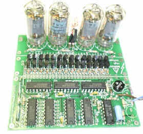
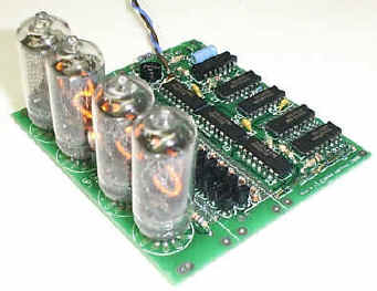
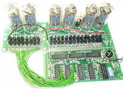
Here are a few assorted pictures to clarify any details not obvious from the layout drawing. Note that there are a couple of slight differences in the positions of a few of the components due to errors on the prototype PCB, and only one of the Columns of neons is fitted.
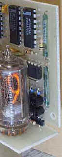
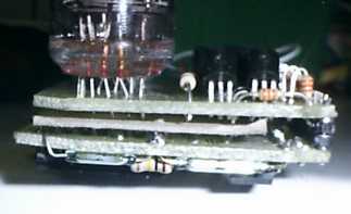
Alternative stacked-PCB version, it only have 3 Tubes so it uses a long NE-2H neon Bulb for the 10 hours digit – this Bulb and the Tubes were scavenged from an old Nixie DVM module and picked up at a radio junk sale :). This PCB has been chopped about a bit to fit the Case! Note the cardboard insulating spacer between PCBs.
Notes on the ready-made PCB
Ready-made PCBs are available from Gary Kaufman in the USA, you can contact him directly at nixie@the-planet.org.
The design for this PCB has been enhanced from the original version to make it as flexible as possible. Changes include the addition of mounting holes, optional voltage doubler for 115V operation, two possible cut-points to subdivide the PCB to suit various mechanical arrangements and a rearranged divider and connection pads to make it easier to add seconds digits for a 6-digit version.
The parts list for this PCB is as was shown above, with the following changes : R14 deleted (R14 is now only used for the 6-digit seconds option). C10 (100 to 220 pF) added – this may be required with some makes of U1/U8 if the ‘hours’ don’t reset correctly from 12 to 1. Note that C5 is missing from silkscreen – it’s next to R12.
The PCB can be built up as a 115 or 230V version. See Voltage_Options.pdf (in nixiepcb.zip) for component differences. Also note that only one option can be fitted!
The PCB can be cut at one or both of two possible lines for flexibility of packaging – see Layout_Options.pdf (in nixiepcb.zip) for some suggested layouts.
Seconds option
The PCB has pads to provide the signals to drive another 2 Nixies for seconds display. These signals are connected to another sixteen driver stages to drive the 2 Tubes. These 2 digits can be built on a second PCB, cut-down as required. Download seconds.pdf for a diagram of the required interconnections. For time setting, in addition to the normal fast/slow set switches, an additional switch is used which freezes the seconds count. A 100 nF capacitor may be required across the ‘Seconds Hold’ switch, depending on the type of switch used, to avoid the count jumping when the switch is operated.
This design can, with some small mods, also be used to drive low-voltage filament displays, like projection units or the light-guide ones, shown below. Assuming a 12V filament display, the basic changes are to use BC548’s instead of MPAS42 drivers (note the different pinout), and reduce the base resistors to about 2K2. The circuit is run from a 9VAC 500mA transformer fed into D4, R1/2/16 are bypassed, D1 omitted and C1 increased to 1000 uF 16V. The CMOS chips will now run at 12V (maximum is 15V so be careful if using higher voltage displays).


Gra & Afch Nixie Clocks
We here at Gra & Afch Design Clocks using our own platform as well as the Arduino platform.
Our Nixie Clocks as well as the Arduino Clocks presented in a separate sections in our shop among other models.
And you can come visit it and look anytime: Arduino Shield Nixie Clocks, Nixie Clocks in Cases, Nixie Clocks without Cases, DIY KITs for Nixie Clocks.