
Power Supplies for Nixie Clocks
MC34063 Based Nixie Power Supply
The scheme for powering your Nixie Tubes Clock from low voltage sources such as batteries or wallcube transformers depicted below:
Here are several Notes on this scheme:
1. All resistors 1/4W, 5% Carbon Film. R3 & R4 1/4W 1% Metal Film.
2. L1 – Bourns SDR1806-221, SDR1307-221, Murata 18R224C, API 4590R-224K, Coiltronics DRA127-221-R, DR127-221-R, UP4B-221-R.
3. Q1 – IRF740A or B, IRF644, FQP16N25, STP17F25 or BUZ73.
4. D1 – BAV21, UF4004, UF4007, MUR140 or MUR160
5. C1 – 220uf, 25V Low ESR. 0.3 Ohms or less.
Next, D2 and Q2 form active pull-down. This allows Q2 to discharge Q1’s gate charge much faster, than R2 (1K) can do by itself. Effectively making it look like a 10 Ohm resistor. But only when swinging down. Swinging up turning ON Q1 then Q2 is out of the picture. This is the beauty of active circuits when efficiency can be as good as 80%. This circuit can deliver close to 45mA (180V out) with 12V in.
Voltages other than 180V can be also used with adjusting R3 or R4 or both. See formulas on drawing below, 250V max with components shown, if need higher, see below:
Adding Multiple Voltages
You can get multiple voltages out of Power Supply described below, MK1.5 and out of most other Nixie Clock Power Supplies by adding multiplier ladders. What’s required is that you need to have access to the pulsed output. If that is done you can get the voltages shown on the drawing below:
You should note that you can get both the Higher positive voltages (+360V and +540V) and Negative voltages (-180V).
If a voltage isn’t quite right you can always fall back on your early electricity classes. Th?venin equivalents then can be used. Suppose you need +450V and the anode resistor is 680K. Make a divider and hook it up to the +540V Supply. The divider will output 450V (unloaded) if you pick 820K, and 3.9M. Also they look to the anode, like a 680K resistor, since 820K in parallel with 3.9M, is 680K. You can always look for a reference to Th?venin if you need more convincing.
If it’s to simple – Avoid it
Avoid “passive pull downs” like depicted in the circuit below:
In this circuit (MK1) the MC34063 can only actively pull-up and turn ON the FET’s gate. Turn-Off is only through R2 (330 Ohm). Turn-Off is critical, because that’s when the high voltage pulse is generated. And you want that to happen as quick and clean as possible. This simpler MK1 circuit can only deliver ~10mA, before the FET gets too hot. It has a poor efficiency (under 60%). The MK1.5 circuit can deliver close to 45mA, at an efficiency near to 80%.
T1 Unitrode UC3843 Based HV Supply
Look at the sheme, depicted below.
You should note the alternate chip to the MC34063. The UC3843 chip both sources and sinks the FET (Q1). In this scheme no other drive components is needed. On the down side it needs at least 9V to work and has internal shutdown circuitry that switches it OFF if the input voltage gets too low.
Discrete HV Power Supply
Here is a High Voltage (HV) Power Supply that uses only discrete components. No ICs is used:
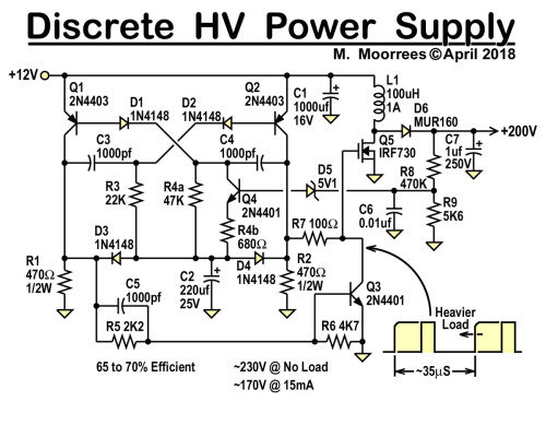
Let’s see what we have here. Regulation is poor relative to IC based supplies but adequate for Nixie Tubes usage. It is also less efficient than most IC based power supplies but comparable with 555 based designs. Maximum recommended output for that scheme is 15mA.
Talking about the scheme itself. It is based around an astable multivibrator using PNP transistors. Regulation is performed by varying the duty cycle, by varying the RC time of R4 and C4. The Q4 acts as a current source for charging C4 and varies with the output voltage. The Higher the voltage the shorter the period that the MOSFET (Q5) is ON. The Q3 is also added to speed up the discharge of the MOSFET’s gate.
Low Cost “FET-less” HV Supply
Mostly all boost type HV switching Supplies are reliant on modern power MOSFETs to act as efficient switches. Though these supplies are relatively inexpensive, the MOSFET usually represents the most expensive component in the supply. Often even more than the controller IC. To make a really cheap Power Supply if you only need a couple of milliampers of current, here is a design that uses less than a dollar worth of parts (as of mid 2019):
Let’s look closer. It can deliver up to 4mA without heating up a common MPSA42 transistor used as the switch. A common base hookup is used for the A42, so faster internal switch of the MC34063 is also in series with the primary current path, since a MPSA42 is a pretty slow transistor. Two common (but very fast – 4ns) 1N4148 diodes used as the HV rectifier and hooked up in series to double the final reverse blocking capability to 200V. The 2mHz coil and MC34063 are the most exotic parts in this design, though both can be easily found on the market. And last one to keep in mind, this scheme is used if not much of a current is needed.