
How to drive a Nixie Tubes
How to drive a Nixie Tube
If you want to build a Nixie display or a Nixie Clock you’ll have to know how to use and drive Nixie Tubes. We will discuss here basic and multiplexed use of the Tubes. There are a number of schematics to illustrate various usages.
1. Direct Control of Nixie Tubes
Most Nixie tubes share the same internal structure: a common anode (positive terminal) and ten individual cathodes (negative terminals), each responsible for displaying one digit from 0 to 9.
Nixie tubes operate at high voltage, typically between 170V and 190V.
⚠️ Caution: Such voltage can be dangerous.
As an example, let’s consider one of the most popular Nixie tubes — IN-14. Read here how to choose the right nixie tube.
To light up a Nixie tube, you will need: a 180V high-voltage power supply, a current-limiting resistor, a switch, and wiring.
Using a current-limiting resistor is strictly mandatory — without it, you risk damaging either your power supply or, more likely, the tube itself.
Each type of Nixie tube requires its own value of anode resistor.
The table below lists typical resistor values for the most common Nixie tubes:
| IN-1 | IN-4 | IN-8(2) | IN-12 | IN-14 | IN-16 | IN-17 | IN-18 | Z573M | Z5660M | Z568M | |
| Ra | 24k | 24k | 24k | 27k | 24k | 33k | 27k | 10k | 27k | 12k | 8.2k |
| Ia | 2.5 – 3mA | 2.5 – 3mA | 2.5 – 3.5mA | 1 – 2.5mA | 2..4mA | 1 – 2mA | 1.5 – 2.5mA | 4 – 8mA | 1.5 – 2.5mA | 3 – 6mA | 4 – 7mA |
For Nixie tubes not listed in the table, the anode resistor can be calculated using the following formula:
Ra = (Vhv – Vs) / Ia, where:
Vhv — supply voltage applied to the anode (from the high-voltage power supply),
Vs — Sustain (Maintaining) voltage,
Ia — allowable anode current.
Values for VS and IA can be found in the datasheet of your Nixie tube.
Unfortunately, not all datasheets specify the sustain (maintaining) voltage, but that is not a problem — it can be easily measured with a voltmeter.
To measure VS, connect the tube to a high-voltage supply through any resistor between 8.2 kΩ and 47 kΩ, and measure the voltage between the anode and cathode when the tube is lit.
You can safely perform a short test even with a non-optimal resistor value — a brief operation in this resistance range will not harm the tube.
As a general guideline:
- for small tubes, use a resistor from 22 kΩ to 47 kΩ,
- for large tubes (with digit height above 0.6 inch), use a resistor from 8.2 kΩ to 12 kΩ.
For larger tubes, use a power resistor with a sufficient power rating; 1 W is usually enough.
For SMD resistors, the appropriate size is 2512.
Example:
For an IN-14 tube powered by a 180V supply,
Ra = (180V-130V)/0.002A = 25 000 Ω (25 kiloohms)
The nearest standard resistor value is 24 kΩ.
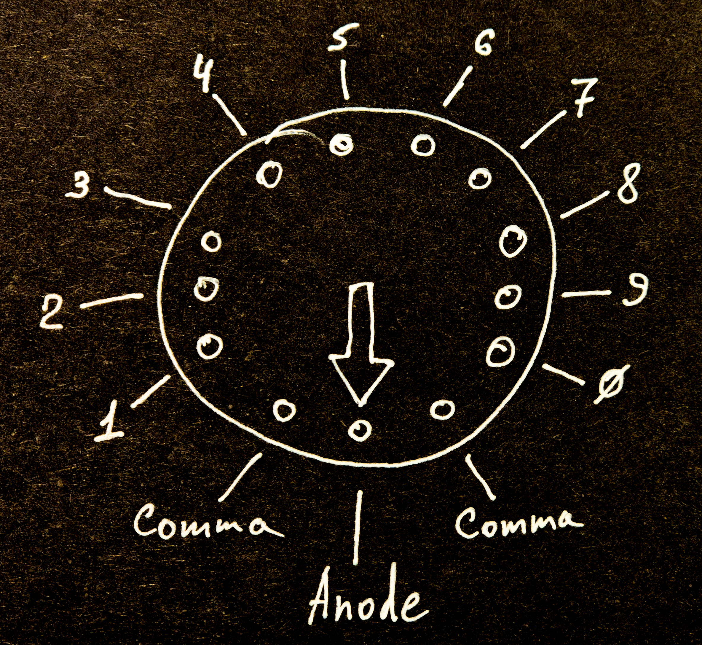
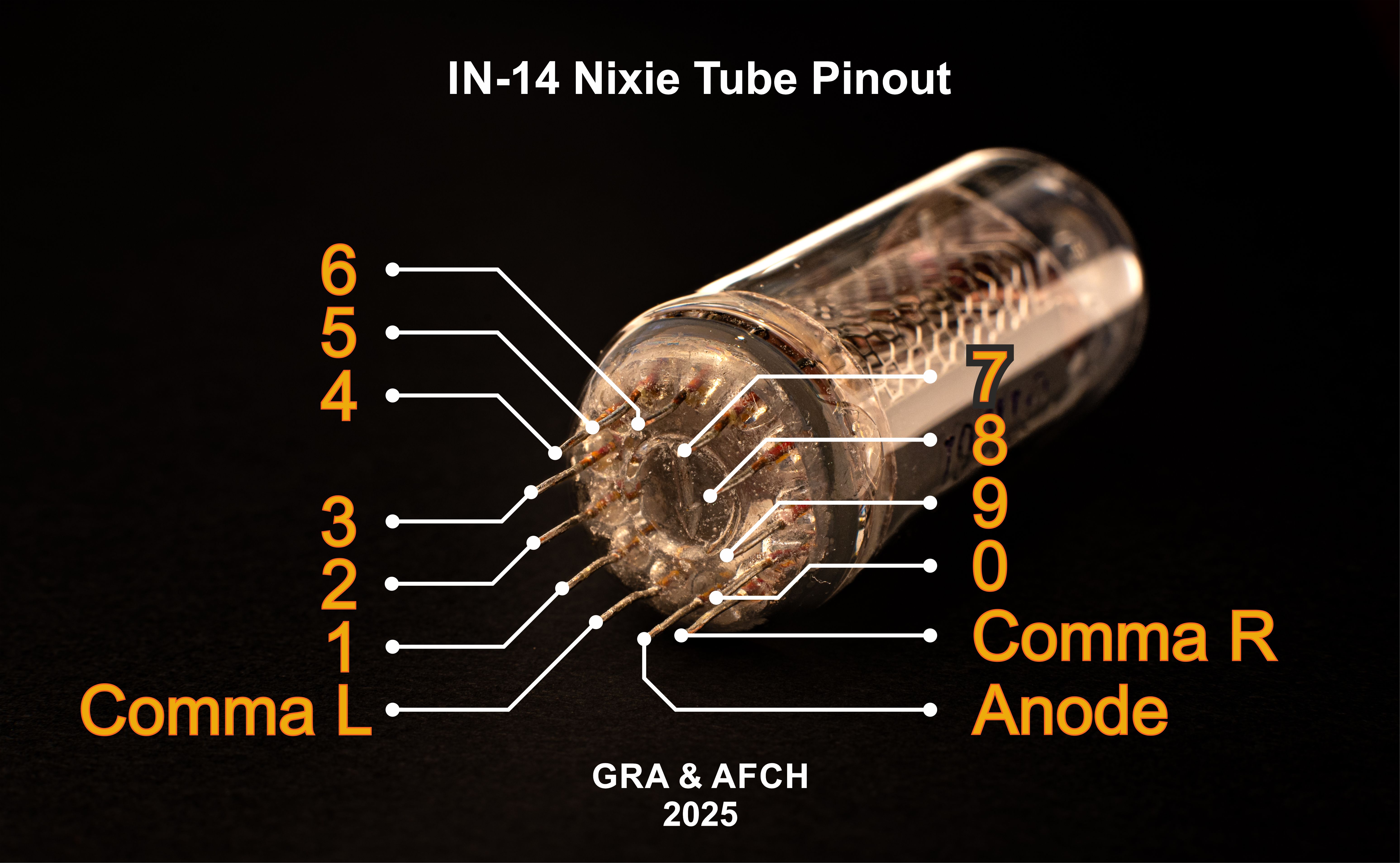
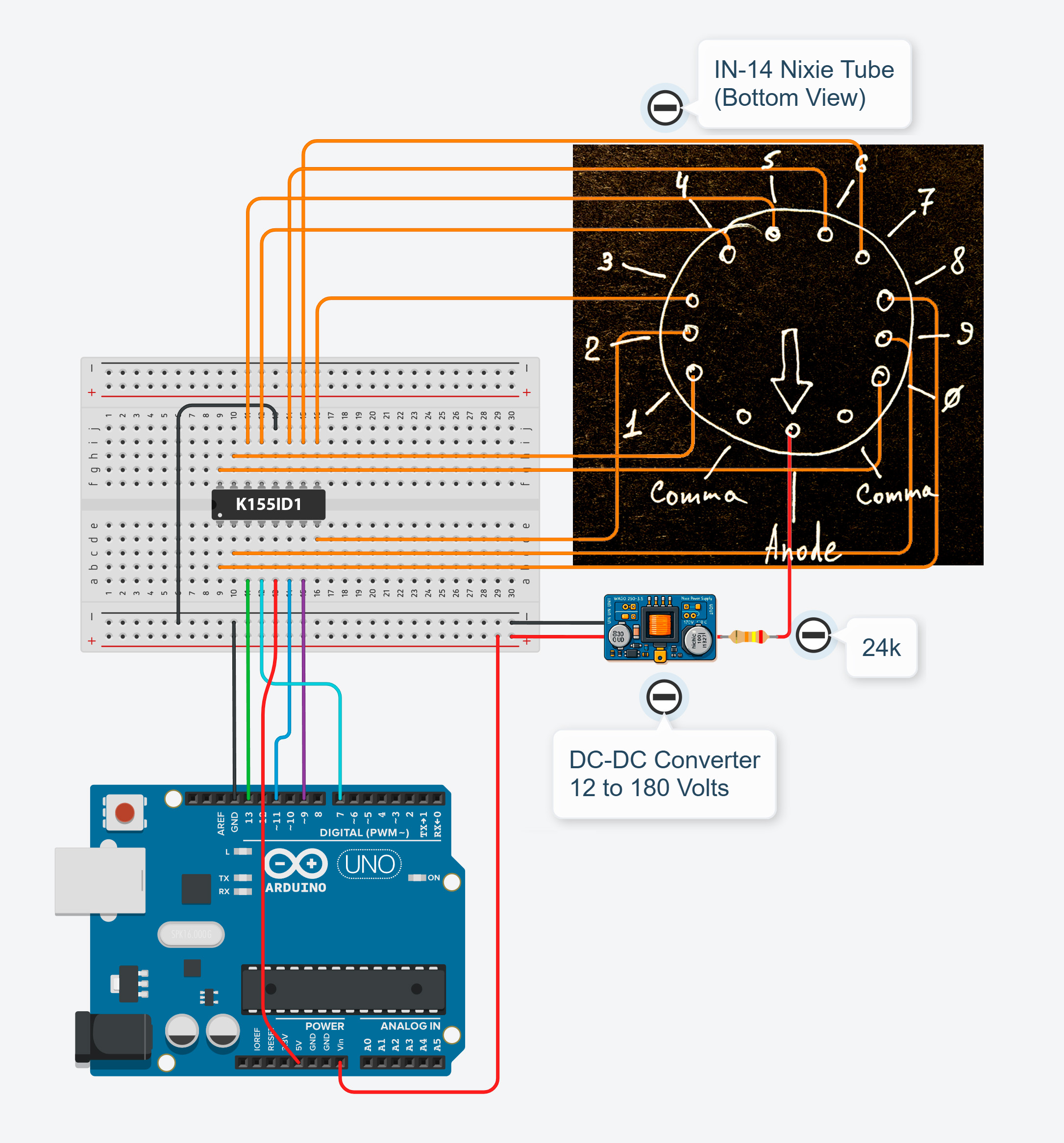
Before we begin wiring our first Nixie tube, we must identify the physical layout and the function of each pin. The first thing to pay attention to is the arrow located on the bottom part of the glass envelope, which points to the pin connected to the tube’s anode. Below is the pinout shown as a diagram (bottom view, from the pin side) and, for maximum clarity, also as a photo.
Now we can proceed with assembling the first circuit:
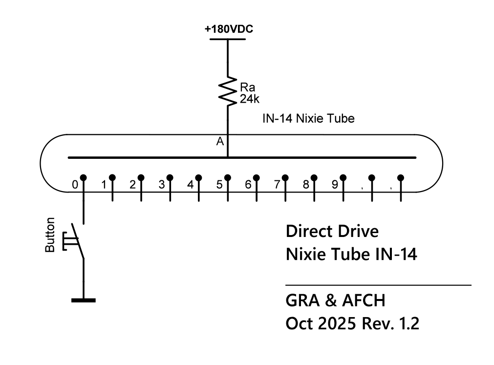
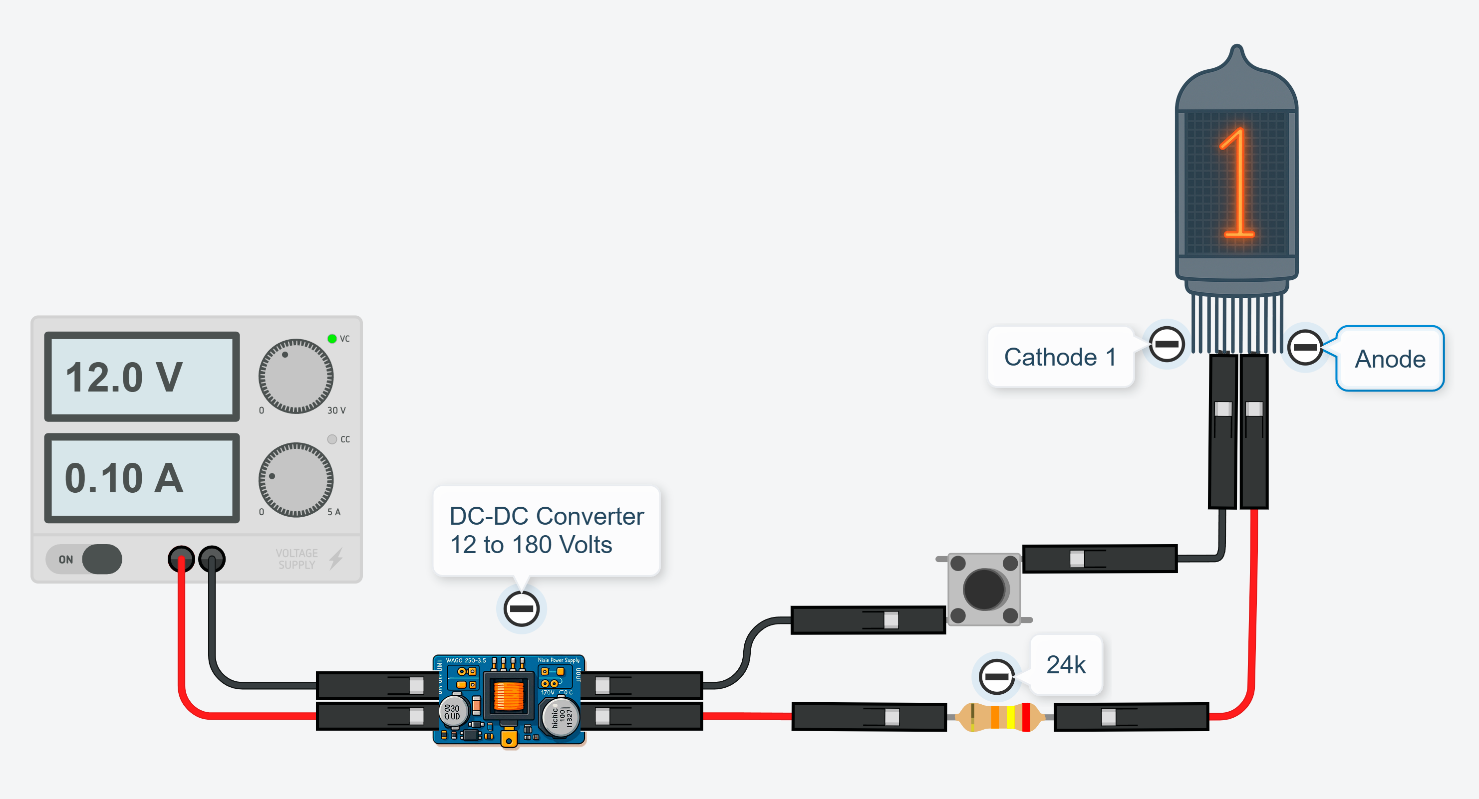
The diagram shows a single push-button, but you can connect as many buttons as you need and light up different digits by pressing them sequentially.
This simple direct control method can be used, for example, in escape rooms or other applications where the tube is operated manually by an operator.
2. Electronic Control of a Nixie Tube
The mechanical switches from the previous example could be replaced with relays, but such a design would be bulky and outdated.
A better approach is to use electronic switches — transistors.
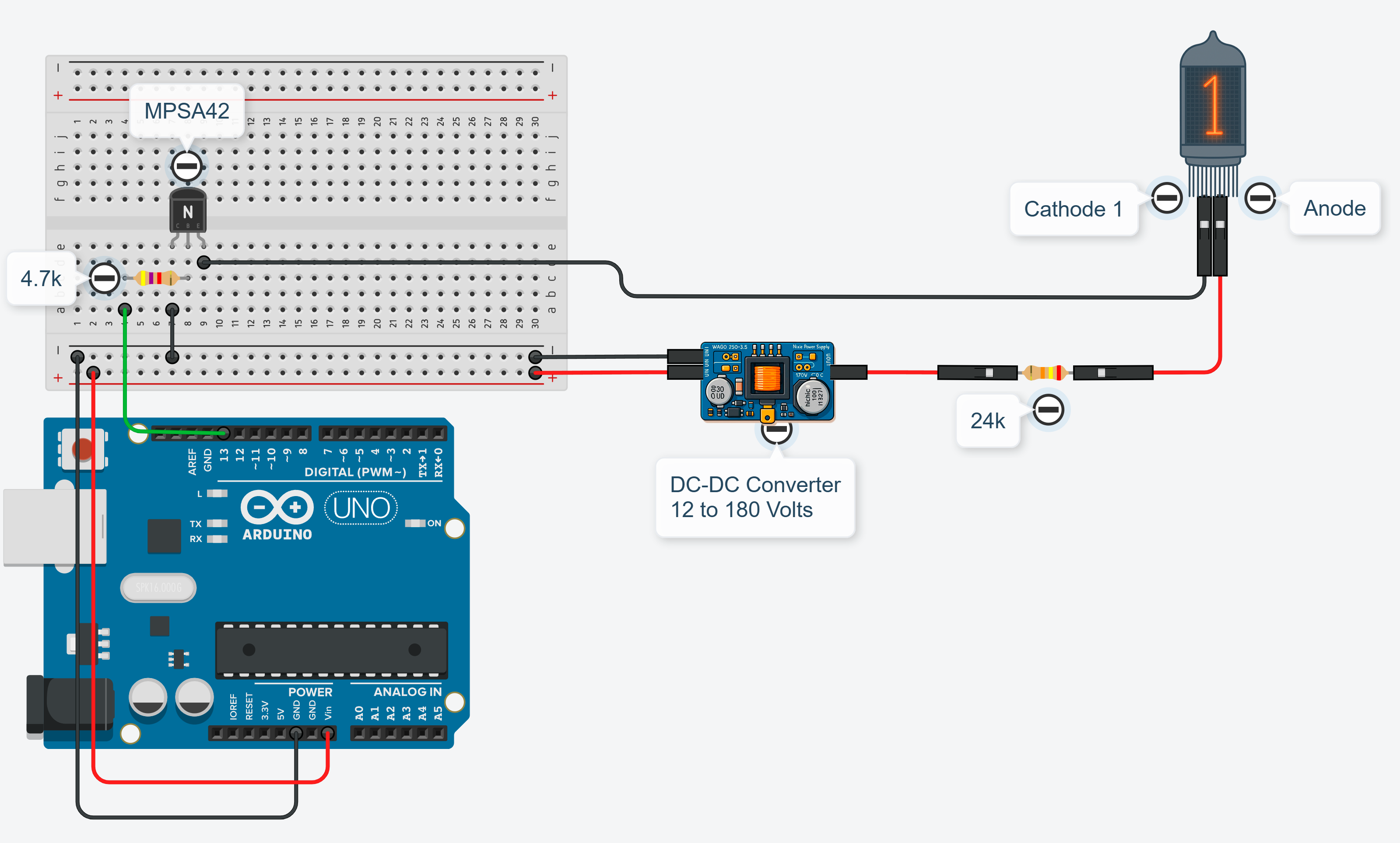
You cannot connect the tube’s cathodes directly to the microcontroller pins, because the tube is driven by a very high voltage (typically 180V), whereas microcontroller pins are rated for a maximum of 5V or 3.3V, depending on the model.
There are transistors, such as PMBTA42 (SMD package) or MPSA42 (Through-hole), which can easily withstand the high voltages used in Nixie tube driving circuits. Any other transistor with a collector-emitter voltage rating (Vce) > 200V can also be used.
This allows you to control a Nixie tube using any microcontroller you prefer — Arduino, ESP32, Atmel AVR, STM32, or even Raspberry Pi.
Below is a typical schematic for driving one Nixie digit using an NPN transistor and a microcontroller:
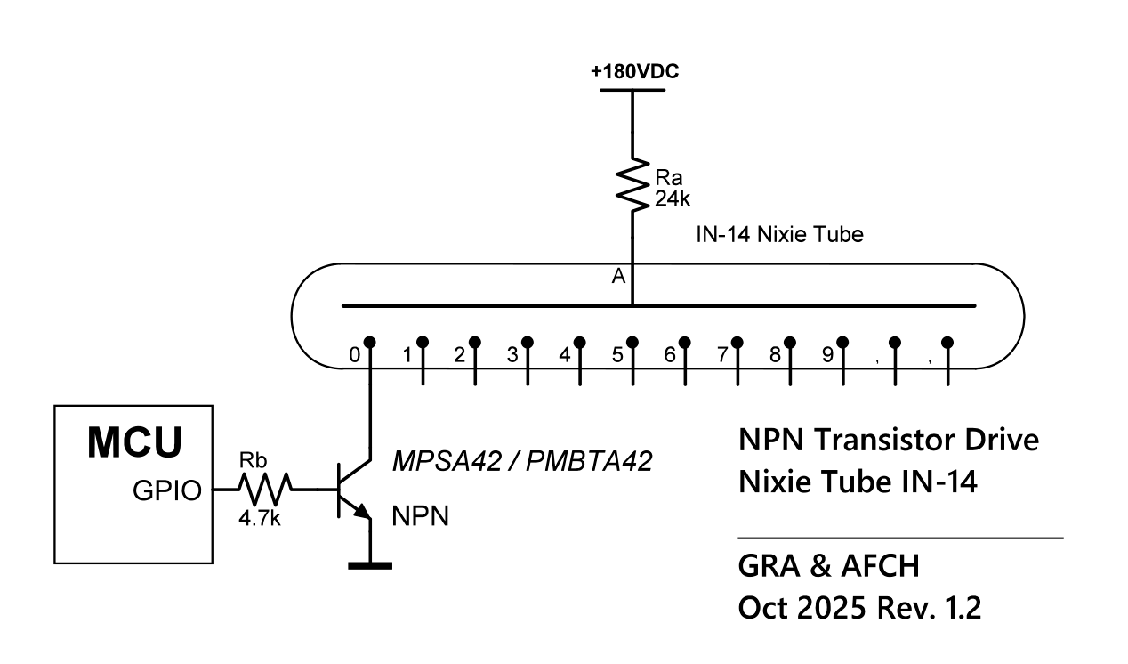
A base resistor must be connected to the transistor’s base, with a value between 3.3 kΩ and 10 kΩ.
Now, by commanding the microcontroller to set a high or low voltage on the pin connected to the transistor’s base (through a resistor), we can turn on or off the specific Nixie tube digit whose cathode is connected to that transistor.
This is a very simple way to drive Nixie tubes, but it also has drawbacks.
If you control only one tube, you need:
- 10 transistors (one per cathode),
- 10 base resistors,
- and 10 GPIO pins on the microcontroller.
However, if you want to control, for example, six tubes (to build a Nixie clock), you will need:
- 60 transistors,
- 60 resistors,
- and 60 GPIO pins.
GPIO (General Purpose Input/Output) pins are microcontroller terminals that can be controlled at our discretion. Typically, this means we can instruct the microcontroller to set the pin either to 0 volts or to the supply voltage (usually 5V or 3.3V). Most available microcontrollers don’t have that many free GPIO pins, and the GPIOs are also needed for scanning the clock control buttons, controlling the separator dots, and so on.
Now that we understand how to control Nixie tubes electronically, let’s move on to control methods that help reduce the number of GPIO pins required.
3. Reducing the Number of GPIO Pins for Nixie Tube Control
To reduce the number of GPIO pins required, shift register ICs such as the SN74HC595 can be used.
This IC receives data serially: information about which of its outputs should be activated and which should be turned off is transmitted in a serial data stream.
To control one such shift register, only three GPIO pins of the microcontroller are required!
A great feature of shift registers is that they can be cascaded, meaning connected in series.
This allows any number of shift registers to be controlled without increasing the number of GPIO pins used by the microcontroller.
This is possible because each shift register has a serial data output, designed to feed data to the next register in the chain.
In other words, information about the state of all outputs is transmitted through a single data line, while the remaining two GPIO pins are control lines used to manage all shift registers simultaneously.
Each SN74HC595 shift register has 8 outputs, which is not enough to fully control all 10 cathodes of a single Nixie tube.
Therefore, two shift registers are required to drive one tube, although the second one will not be fully utilized — only 2 of its outputs will be used.
The remaining 6 outputs can then be used to control the first six cathodes of the next Nixie tube, and so on.
Thus, if we want to control six Nixie tubes (a total of 60 cathodes), we will need 8 shift registers, providing 64 outputs in total — 4 outputs more than required.
These extra 4 outputs can be conveniently used to control the separator dots between the hour and minute indicators, and between the minutes and seconds.
To transfer data from the microcontroller (for example, Arduino Uno) to the shift registers, it is convenient to use the hardware SPI interface:
- MOSI output connects to SER (pin 14),
- SCK output connects to CLK (pin 11),
- SS output connects to RCLK (pin 12).
The remaining inputs of the shift register should be connected as follows:
- OE (pin 13) to GND,
- SRCLR (pin 10) to +5 V.
Since the shift registers operate at low voltage, while the Nixie tubes require high-voltage control, we again need to use high-voltage transistors.
This time, the transistors are connected to the outputs of the shift registers, rather than directly to the microcontroller.
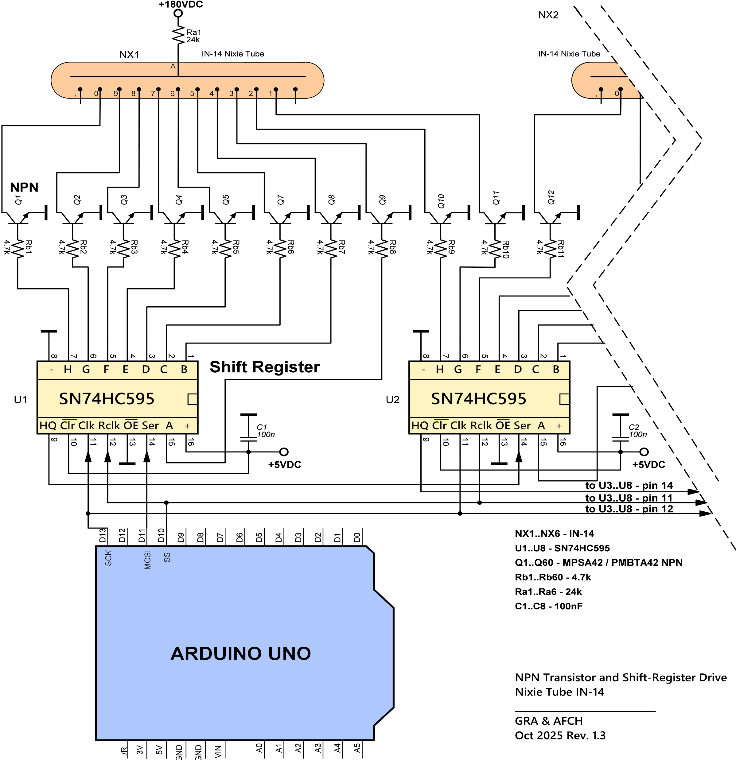
The main drawback of this circuit is that, just like in the previous one, we still need 60 transistors and 60 base resistors to control six Nixie tubes.
4. Specialized IC Drivers for Nixie Tube Control
4.1 BCD-to-Decimal Decoder
There are specialized ICs designed specifically for driving Nixie tubes, such as the SN74141 and its more common Soviet counterpart K155ID1, which is also available for purchase on our website.
These driver ICs contain built-in high-voltage transistors and provide 10 output channels, which is exactly the number needed to control a single Nixie tube.
The presence of integrated high-voltage transistors eliminates the need for 10 discrete transistors (and corresponding resistors) that were required in the previous circuit.
Such ICs are Binary-Coded Decimal (BCD) to Decimal decoders.
Each decoder requires four GPIO pins from the microcontroller, since the input data is represented in binary form from 0 to 9, and the number 9 in binary requires 4 bits.
The binary number applied to the input effectively determines which output line will be activated.
Since one SN74141 or K155ID1 IC is required to drive one Nixie tube, controlling six Nixie tubes will require six such ICs.
Because each IC requires four GPIO pins, the total number of GPIOs needed from the microcontroller will be:
6 × 4 = 24 GPIO pins.
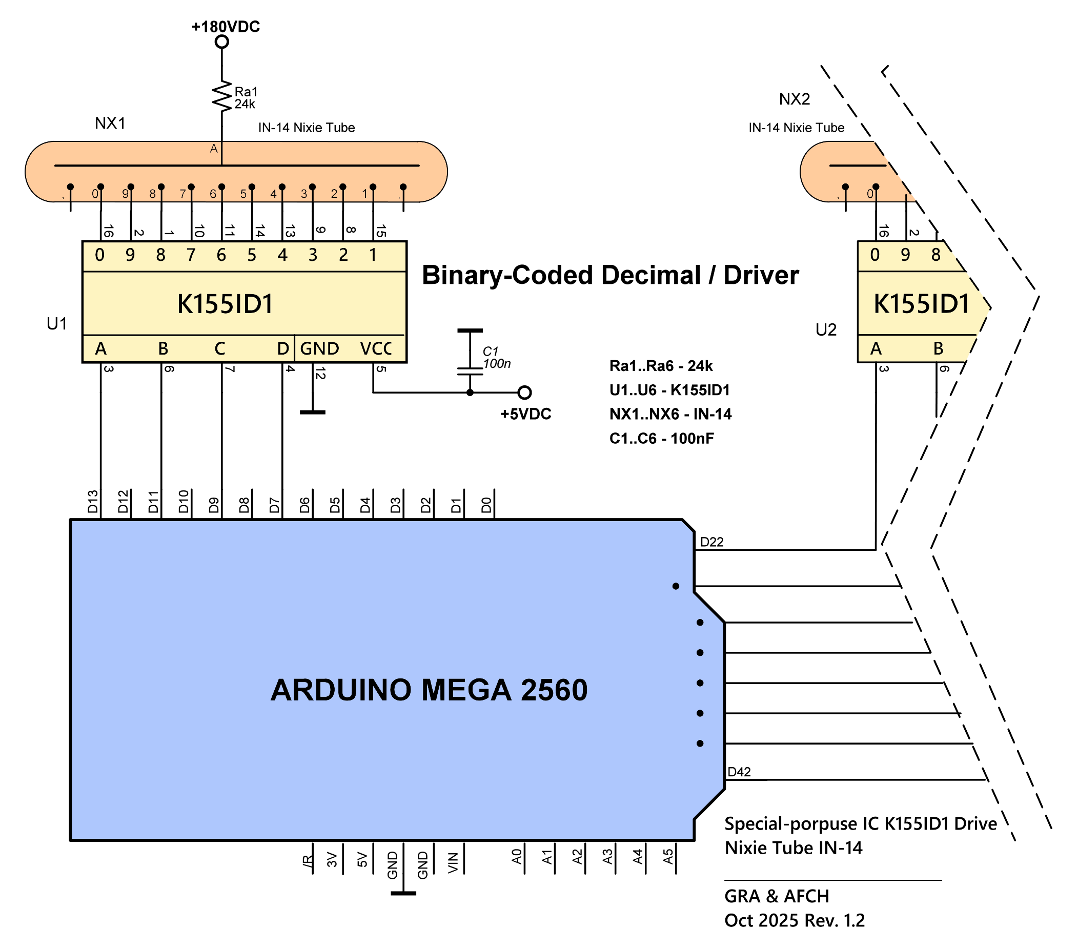
This configuration is perhaps the simplest both in terms of understanding and assembly, as well as in programming the microcontroller.
However, it is not ideal — for example, the Arduino Uno provides only 19 GPIO pins, while this circuit requires 24.
This means a 6-tube Nixie clock cannot be built using this approach with an Arduino Uno.
Nevertheless, this circuit can be used to build a 4-tube Nixie clock controlled by an Arduino Uno, with 3 GPIOs left unused, which can be used, for instance, for clock control buttons.
If we add shift registers such as the SN74HC595 (as described in section 3), the number of required GPIO pins can be significantly reduced.
Each shift register has 8 outputs, so to control 24 signal lines, we need:
24 / 8 = 3 shift registers.
Since shift registers can be connected in cascade, controlling three of them still requires only 3 GPIO pins from the microcontroller — the same as controlling a single one.
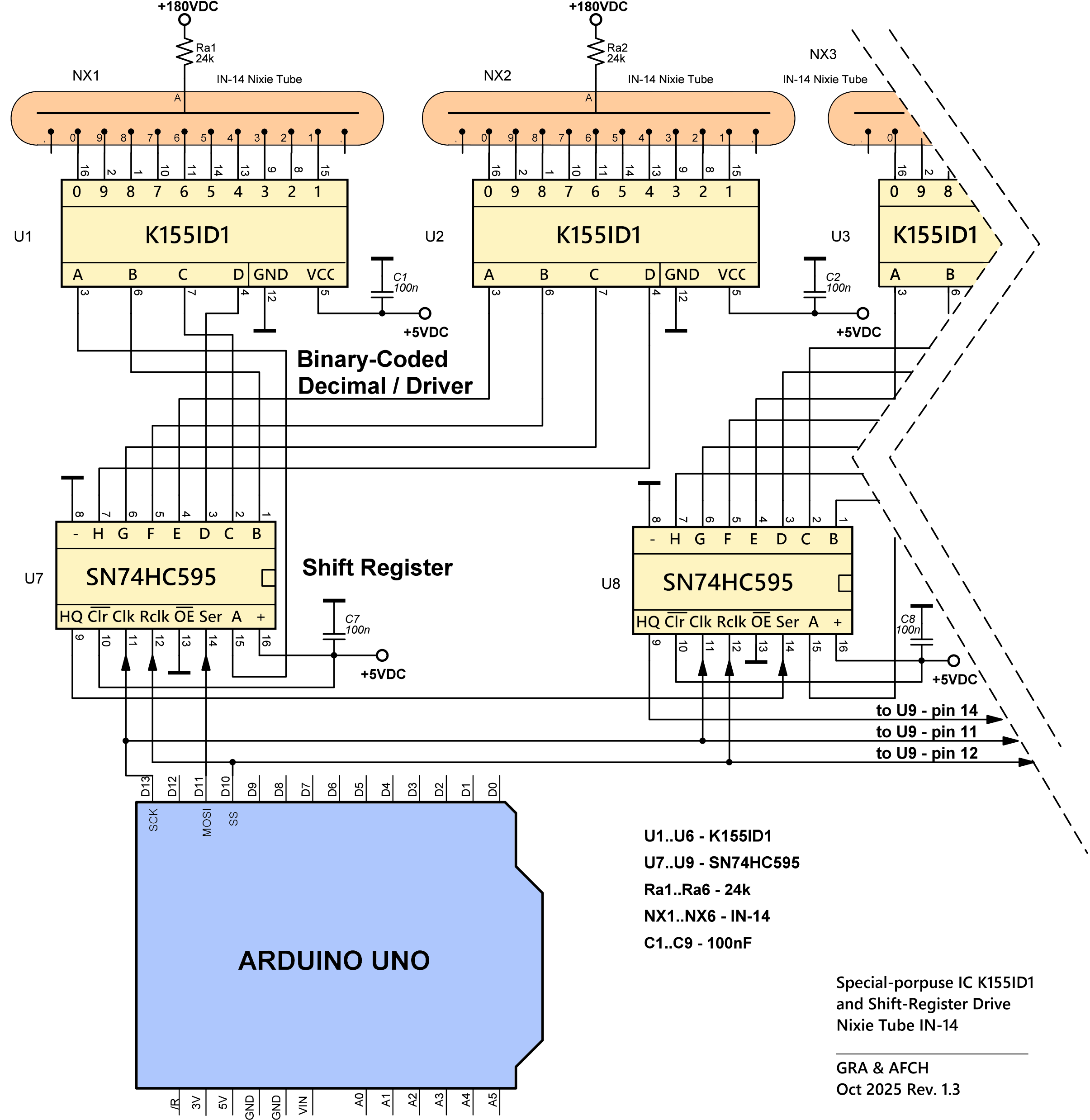
Thus, it becomes possible to build a 6-tube Nixie clock even with a simple Arduino Uno.
The downside of this approach is the large number of ICs: six BCD decoders and three shift registers, giving a total of nine ICs.
In the next section, we will describe how the circuit can be simplified even further by reducing the number of components used.
4.2 High-Voltage 32-Channel Serial-to-Parallel Converter
The simplest way to minimize the number of components is to use specialized high-voltage 32-bit shift register ICs manufactured by Microchip, such as the HV5122 or HV5222.
Each of these ICs provides 32 high-voltage outputs and can also be connected in cascade, without increasing the number of GPIO pins required from the microcontroller.
In practice, only two such ICs are needed — they provide a total of 64 outputs, which is sufficient for all 60 cathodes of six Nixie tubes, with 4 outputs remaining for controlling the separator dots between hours and minutes, and between minutes and seconds.
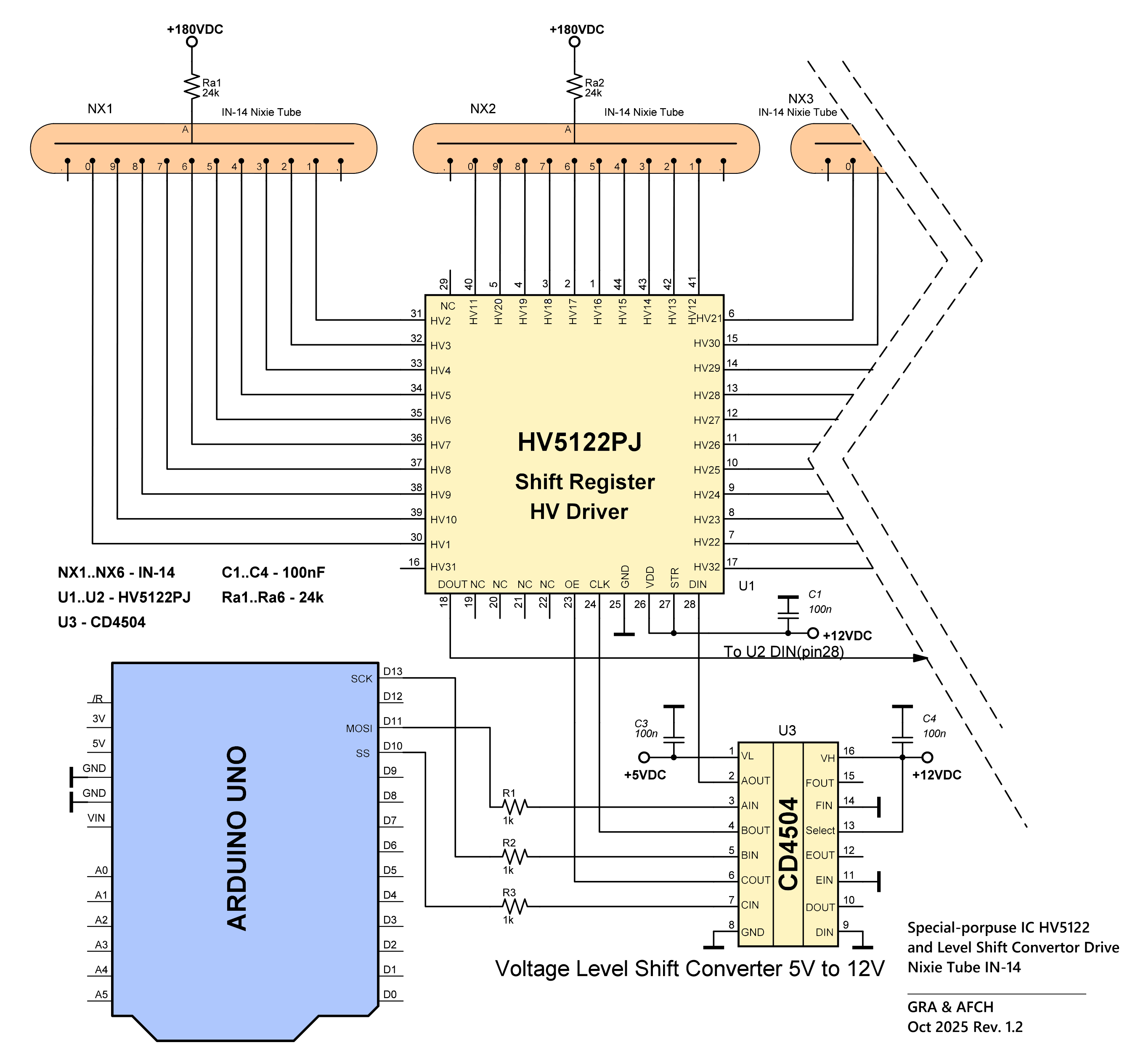
However, this configuration also has some drawbacks:
- These ICs require 12 V logic-level control signals, while popular microcontrollers such as the Arduino Uno and Arduino Mega provide only 5 V logic levels.
Therefore, a level shifter, such as the CD4504, must be added to the circuit.
Fortunately, regardless of how many HV5122 (or HV5222) ICs are used, only one level shifter is required. - The cost of these high-voltage driver ICs is relatively high.
Here you can take a look at a clock built using this schematic.
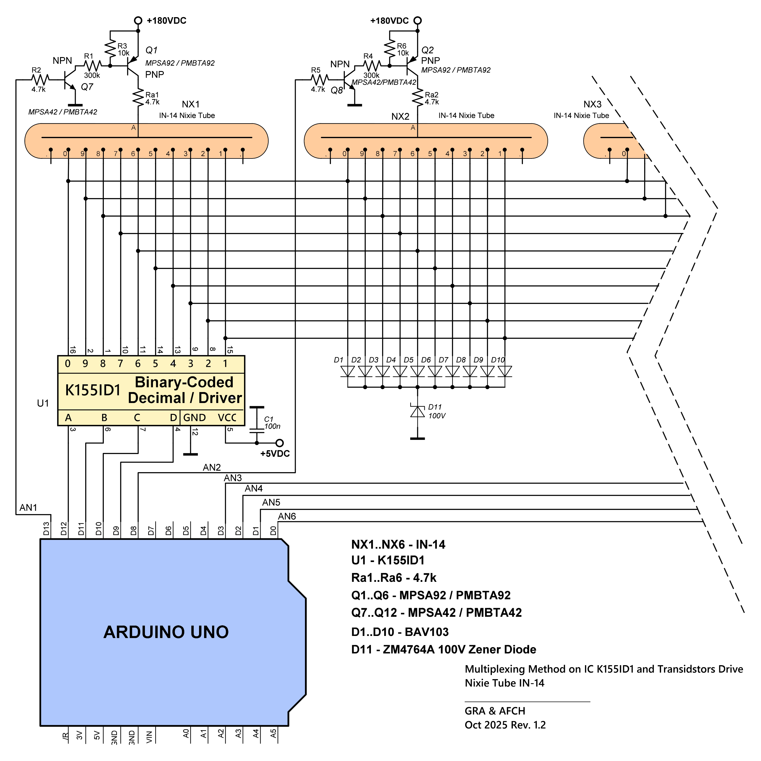
5. Multiplexing
The circuit described in the previous section (with the BCD-to-decimal decoder K155ID1) can be modified in such a way that instead of using six decoder ICs, only one is required!
The multiplexing method consists in connecting identical cathodes of all Nixie tubes in parallel. To prevent identical digits from lighting up on all tubes simultaneously, power is applied to the anodes one at a time. In other words, at any given moment, only one of the six tubes is illuminated.
To control the anode supply voltage, six high-voltage NPN transistors and six high-voltage PNP transistors are required — one complementary pair per tube anode. The NPN transistors can be the same as those used earlier in this article — MPSA42, while the PNP transistors can be MPSA92 or PMBTA92 (SMD)
Thus, this configuration requires only 10 GPIO pins from the microcontroller:
4 GPIOs for controlling the K155ID1 and 6 GPIOs for controlling the tube anodes.
This design is particularly attractive because it uses a minimal number of components, wires, and interconnections. The simplicity of the circuit even allows for point-to-point wiring, i.e., it can be assembled without a printed circuit board.
Ten diodes and one 100 V Zener diode are intentionally added to this circuit, since without them a faint glowing haze would appear inside the tubes.
An unexpected and pleasant feature of this configuration is that the tubes have the longest service life when operated in this way.
The main drawback of this circuit is the relatively complex control algorithm required for multiplexing, which may be difficult for beginners. However, you can study and reuse our implementations of such algorithms in our GitHub projects, for example in our NCM109 4xx Nixie clock board project: DIY KIT for IN-14 Nixie Clock
GRA & AFCH Nixie Clocks
We here at Gra & Afch offer a variety of parts for Nixie Clocks.
As well as Ready-to-Use assembled Clocks, Cases and DIY KITs that are presented in a separate sections in our shop.
And you can come visit it and look for yourself anytime: Spare parts, Nixie Tubes, Nixie Clocks without Cases, Nixie Clocks in Cases, DIY KITs for Nixie Clocks, Cases for Nixie Clocks.