

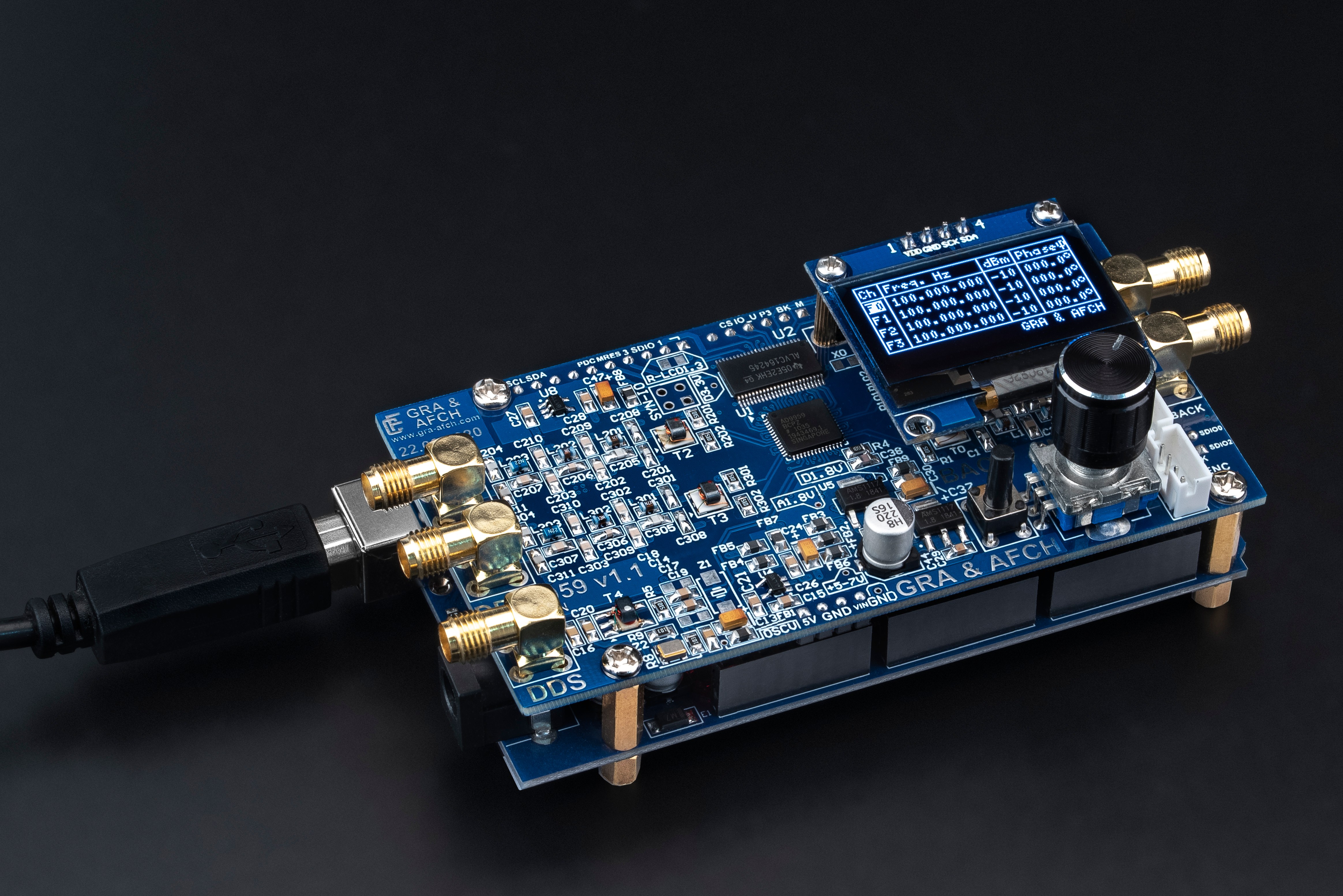
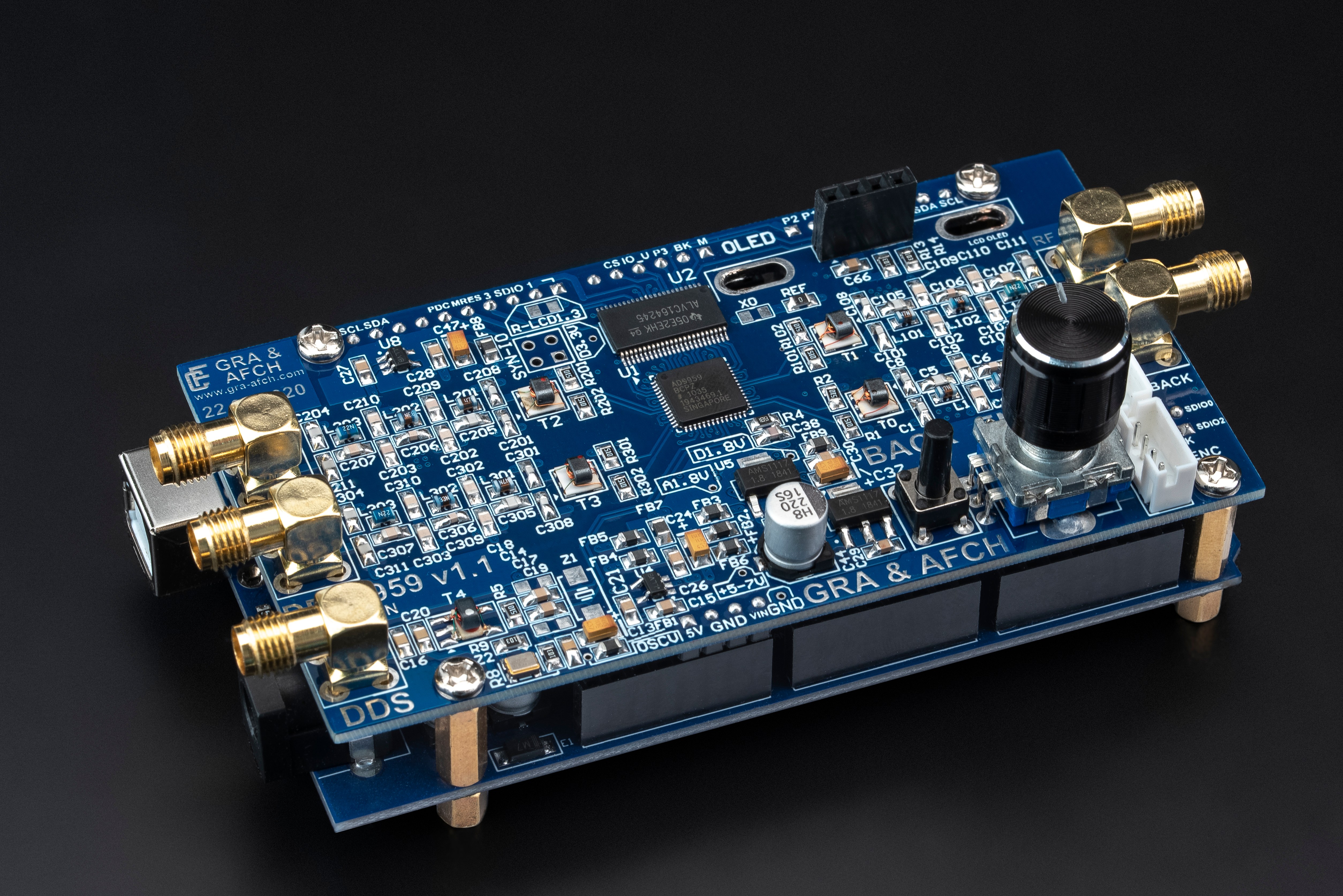
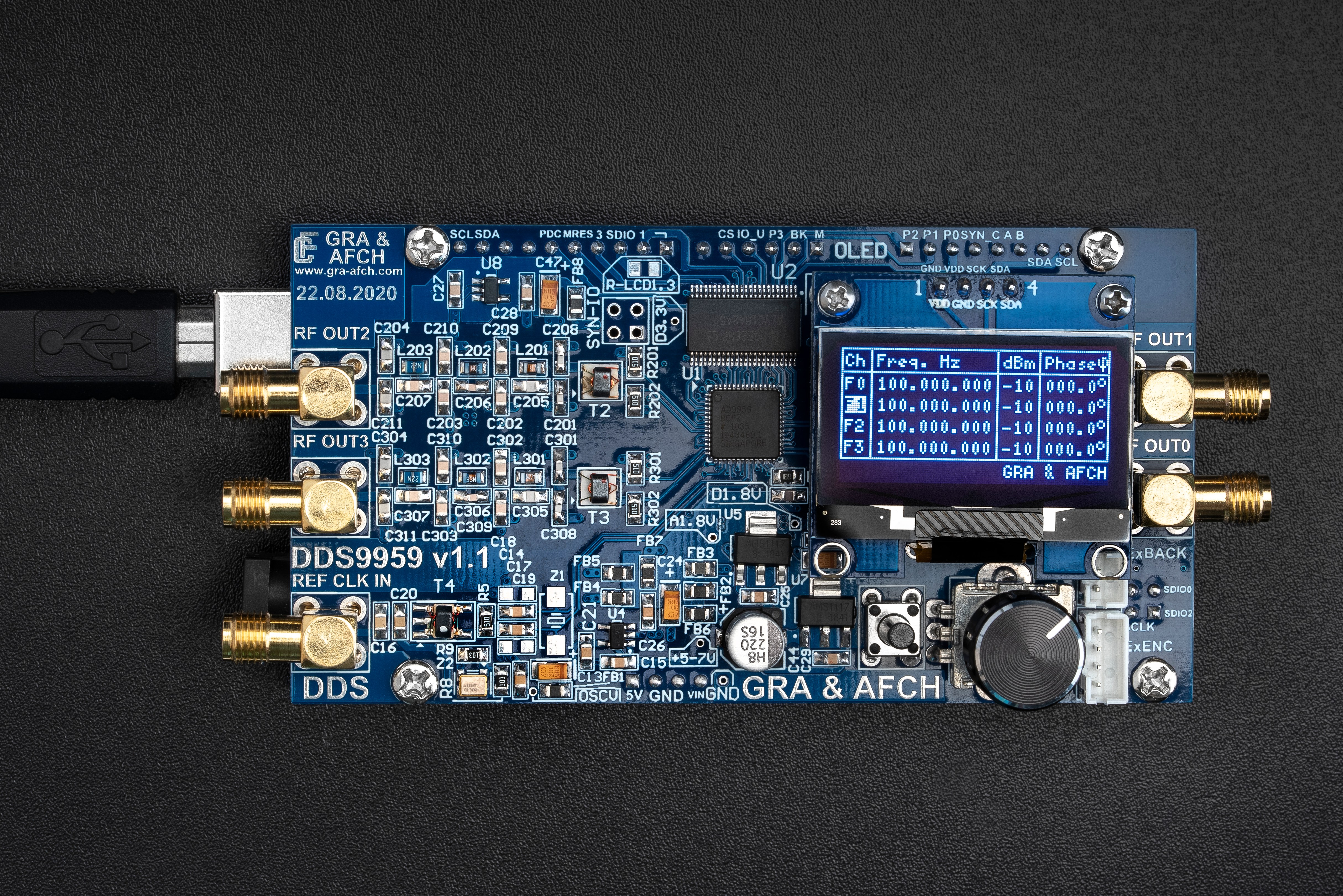
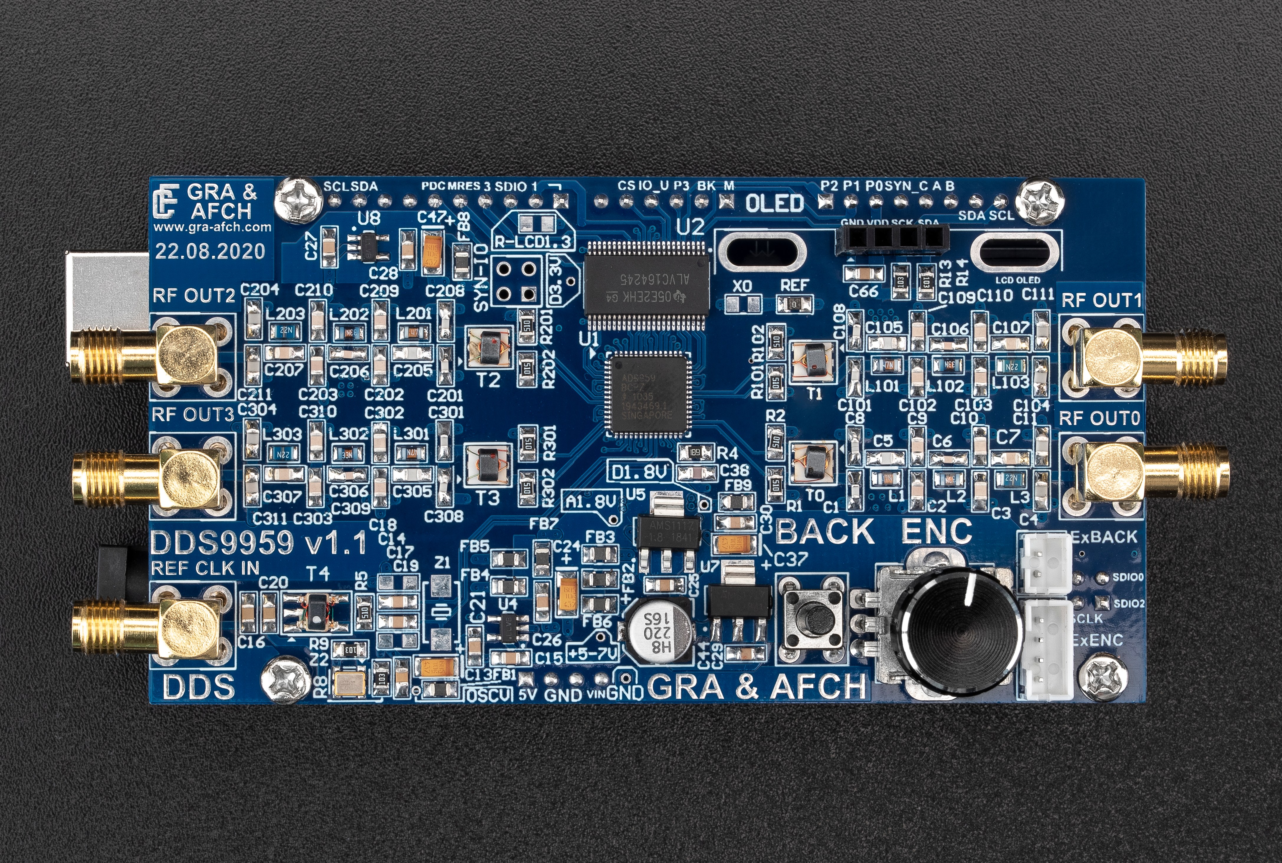
DDS AD9959 Arduino Shield RF Signal Generator 4 Synchronized DDS Channels [225MHz, @600 MHz Core Clock, Low Spurs, Low Harmonic]
Units Sold: 213
DDS (Direct Digital Synthesis) Analog Devices AD9959 4 Synchronized DDS Channels
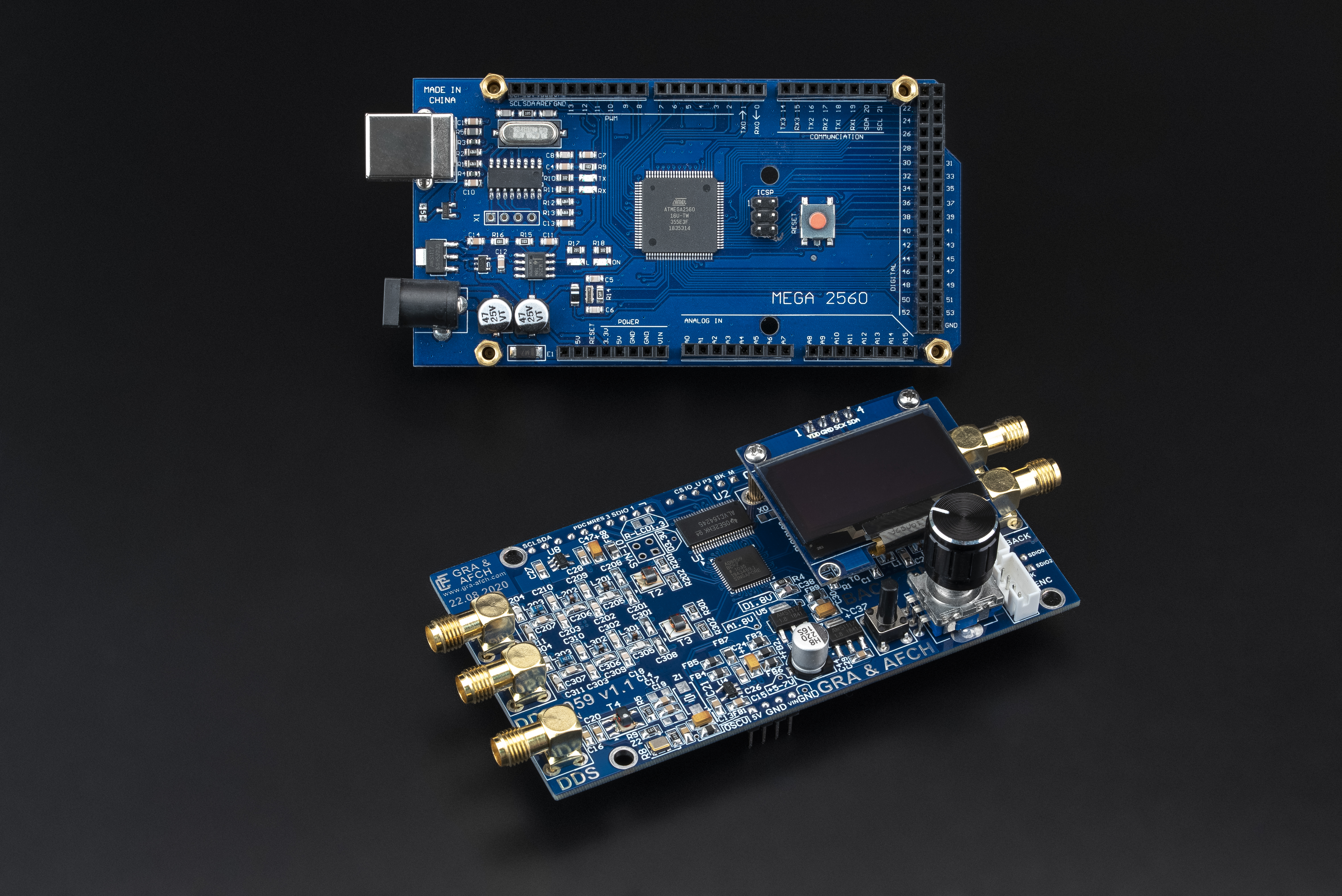
Arduino Shield Easy connection to Arduino MEGA 2560 without additional wires and converters
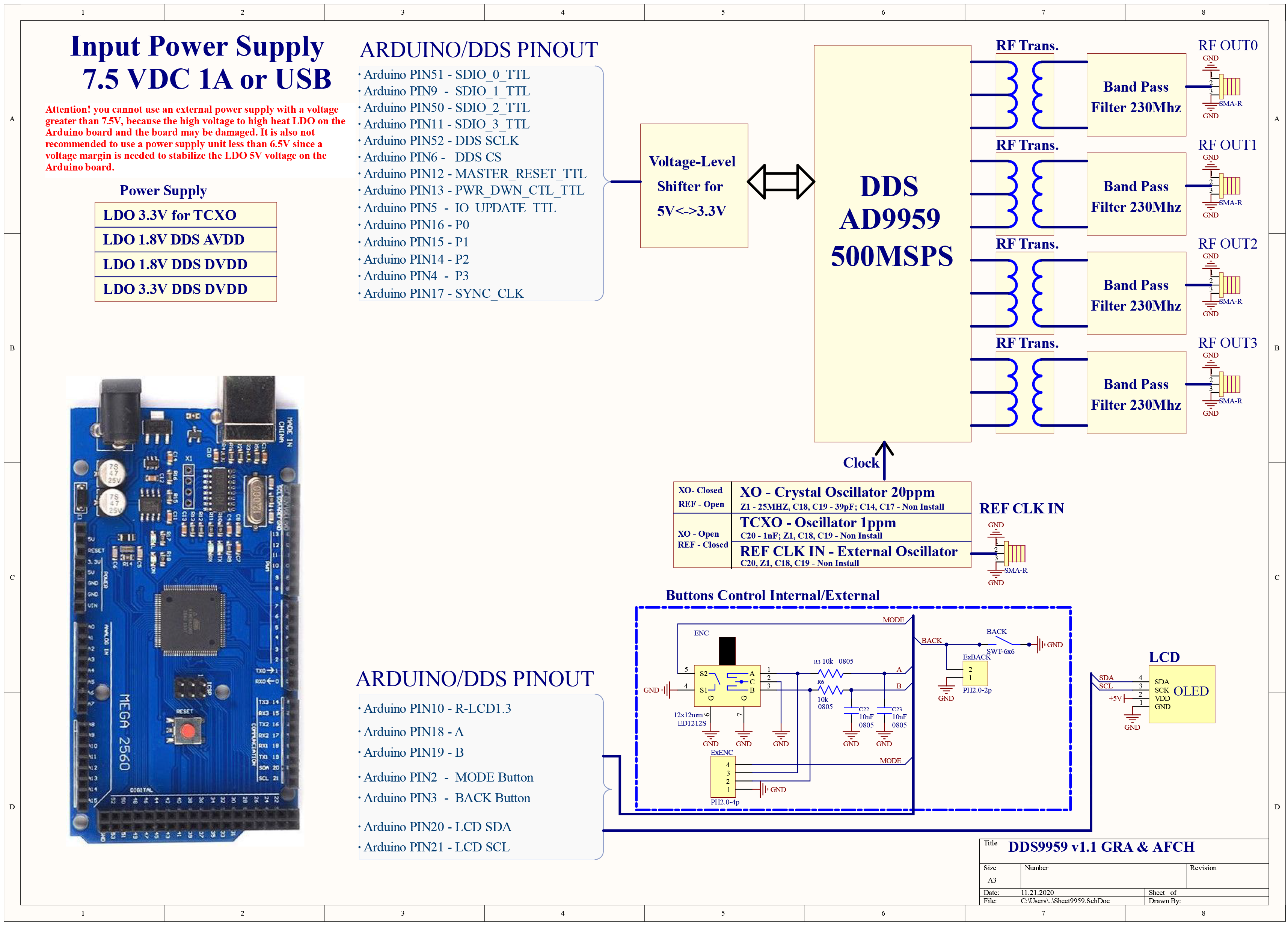
All functions of the DDS AD9959 are brought to the contacts of the Arduino MEGA
With this you can fully reveal all the capabilities of the DDS AD9959 Shield
PCB, Design, Schematics, Case and Software made by GRA & AFCH
$189.95 – $269.95
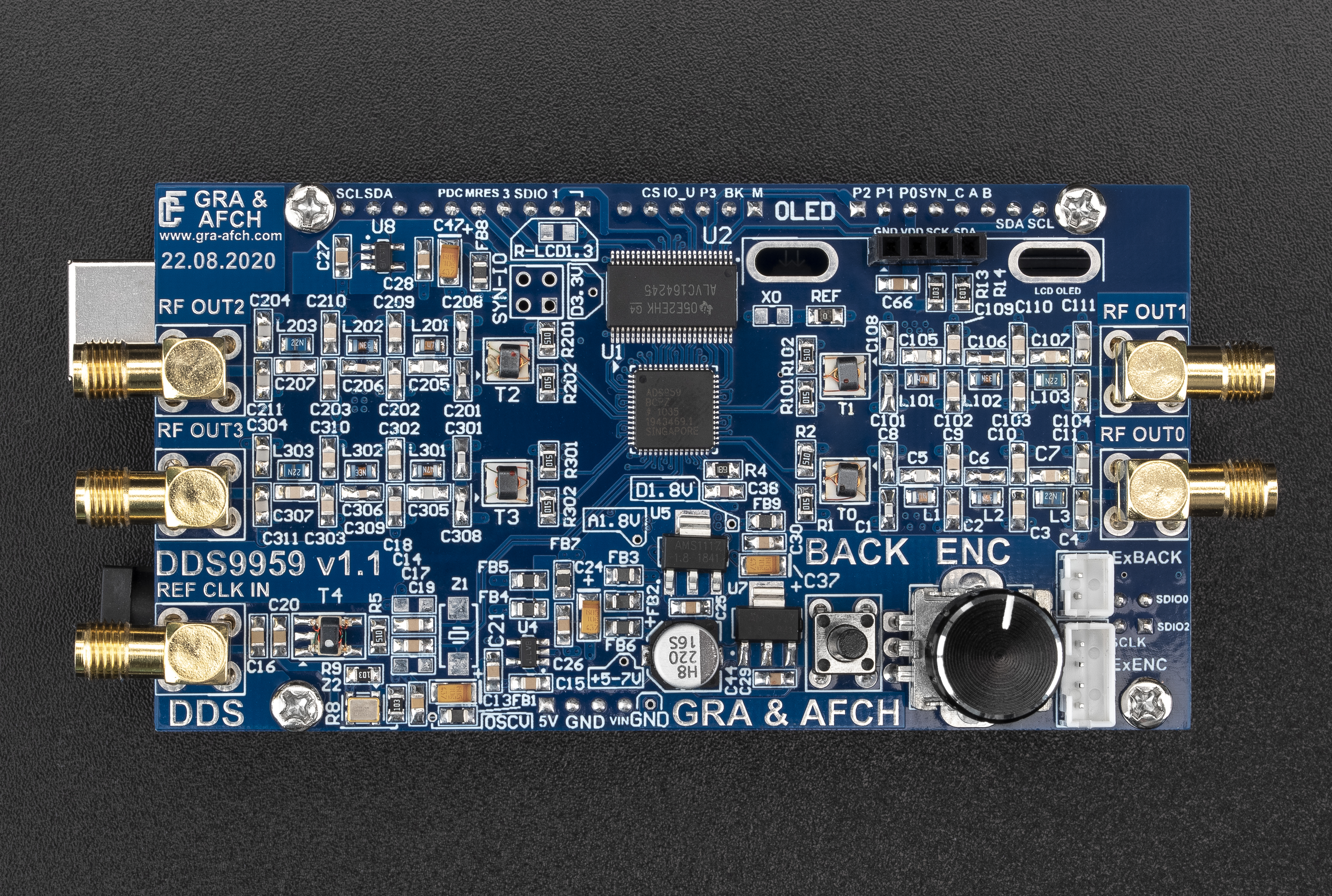
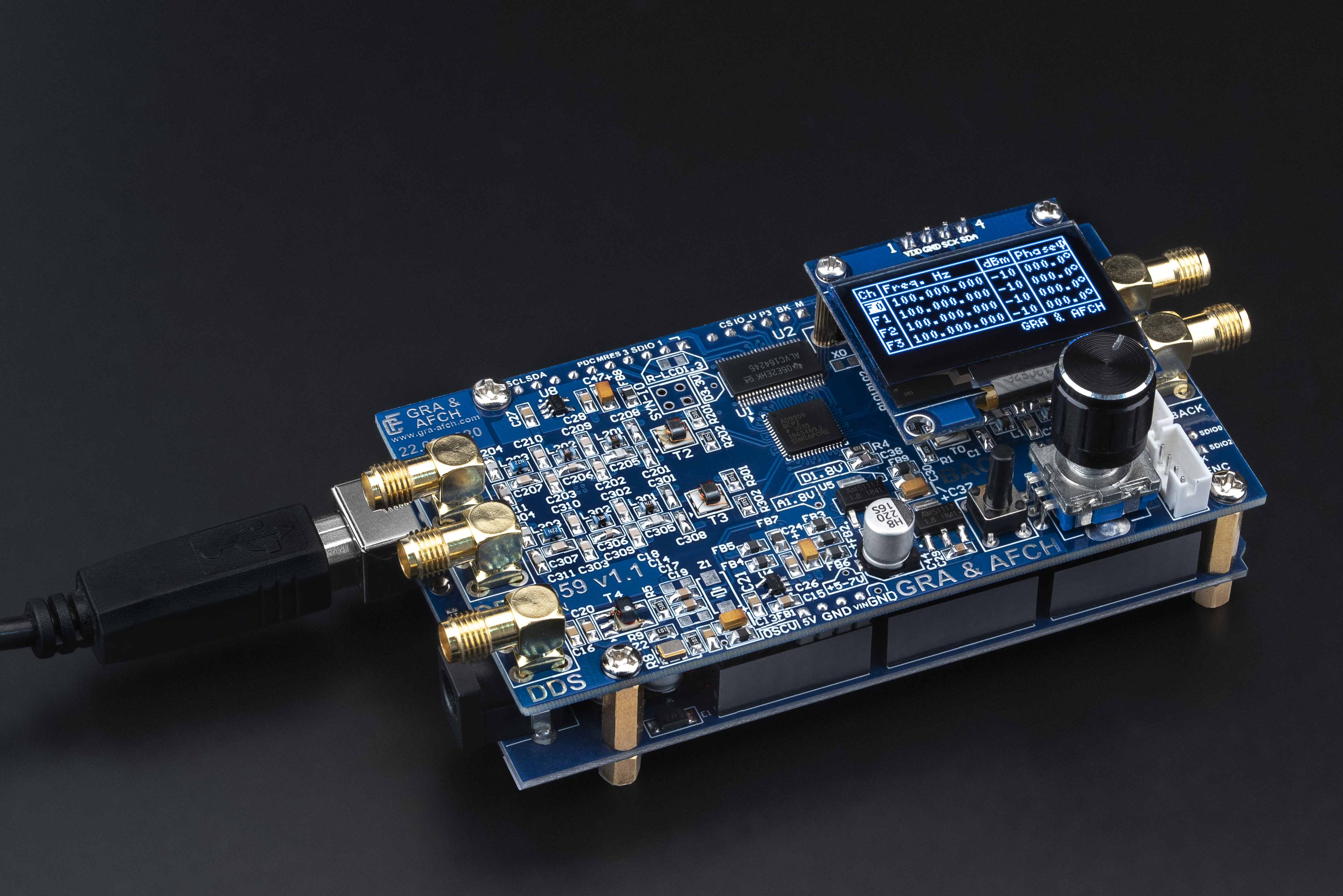
DDS AD9959 4 Synchronized channels Arduino RF Signal Generator Shield
DDS (Direct Digital Synthesis) Analog Devices AD9959 Arduino Shield by GRA & AFCH
Easy connection to Arduino MEGA 2560 without additional wires and converters
All functions of the DDS AD9959 are brought to the contacts of the Arduino MEGA
With this you can fully reveal all the capabilities of the DDS AD9959 Shield
Opensource Software available on our GitHub repository: https://github.com/afch/DDS-AD9959-Arduino-Shield
Video review on our YouTube channel : https://www.youtube.com/watch?v=HpigQwjc9mg&feature=youtu.be
Download page for the DDS AD9959: https://gra-afch.com/Downloads/RF Units/DDS AD9959 v1.1

Listing includes:
- RF AD DDS Unit [AD9959 Shield Board]
- Display [OLED] (optional, choose in selector)
- Clock Source (XO, TCXO, EGEN) (optional, choose in selector)
- Arduino Control Board [MEGA 2560] (optional, choose in selector)
- Power Supply [DC 7.5V/2A] [US, EU, UK] [AC plug] (optional, choose in selector)
- Operating Manual
we cogently recommend using
Low-Pass Filters and RF Amplifiers
with our DDS AD RF Shields:
RF Amplifier 8-2000 MHz, GAIN = 20 dB, P = +20 dBm MMIC MRFA89 SOT-89
for optimal DDS performance
we recommend using high stability
Low Phase Noise external Oscillators:
RCLN500D-5 500 MHz Ultra Low Phase Noise Reference Oscillator -152 dBc/Hz @ 10kHz
RCLN500C 500MHz Low Phase Noise Reference Oscillator -145dBc/Hz @ 10kHz
Custom design:
We are offering custom design development for this Unit for 1200$
This comes with condition that at least 10 pieces of them will be ordered then
Dear customers!
If you have ANY questions, PLEASE ASK us.
If you have ANY questions, PLEASE ASK us.
Key Benefits:
- Convenient and fast control with an encoder.
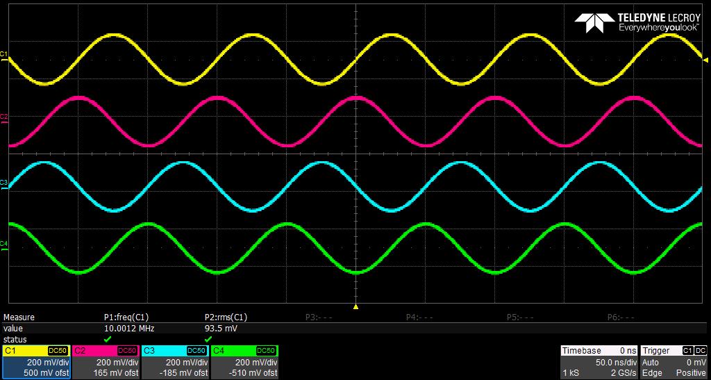
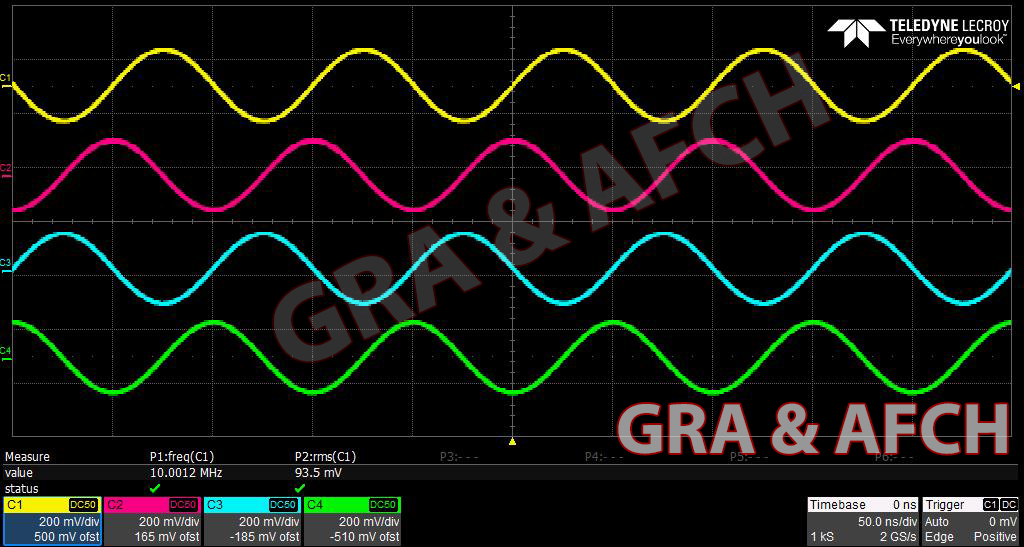
- 4 synchronized DDS channels 225MHz @ up to 600 MSPS
- Low harmonics no more than -60 dBc. An output RF transformer is used for the correct operation of the current mirror.
- Small spurs.
- 4 layer board. Signal lines TOP and Bottom, inner layers Ground and Power.
- Low Noise LDO Stabilizers.
- Separate power supply for all analog and digital lines (1.8V and 3.3V), 5 pcs IC voltage stabilizers are used. Additionally, there is an RF Ferrite bead interchange.
- High-speed decoupling Level converter and TTL 5V matching.
Types of possible reference oscillators (choose one of them in the selector):
- XO – Crystal 25 MHz 20 ppm internal oscillator with PLL up to 600 MHz.
- TCXO – 50MHz (Supports 10 – 125 MHz) 1 ppm external oscillator PLL up to 600 MHz.
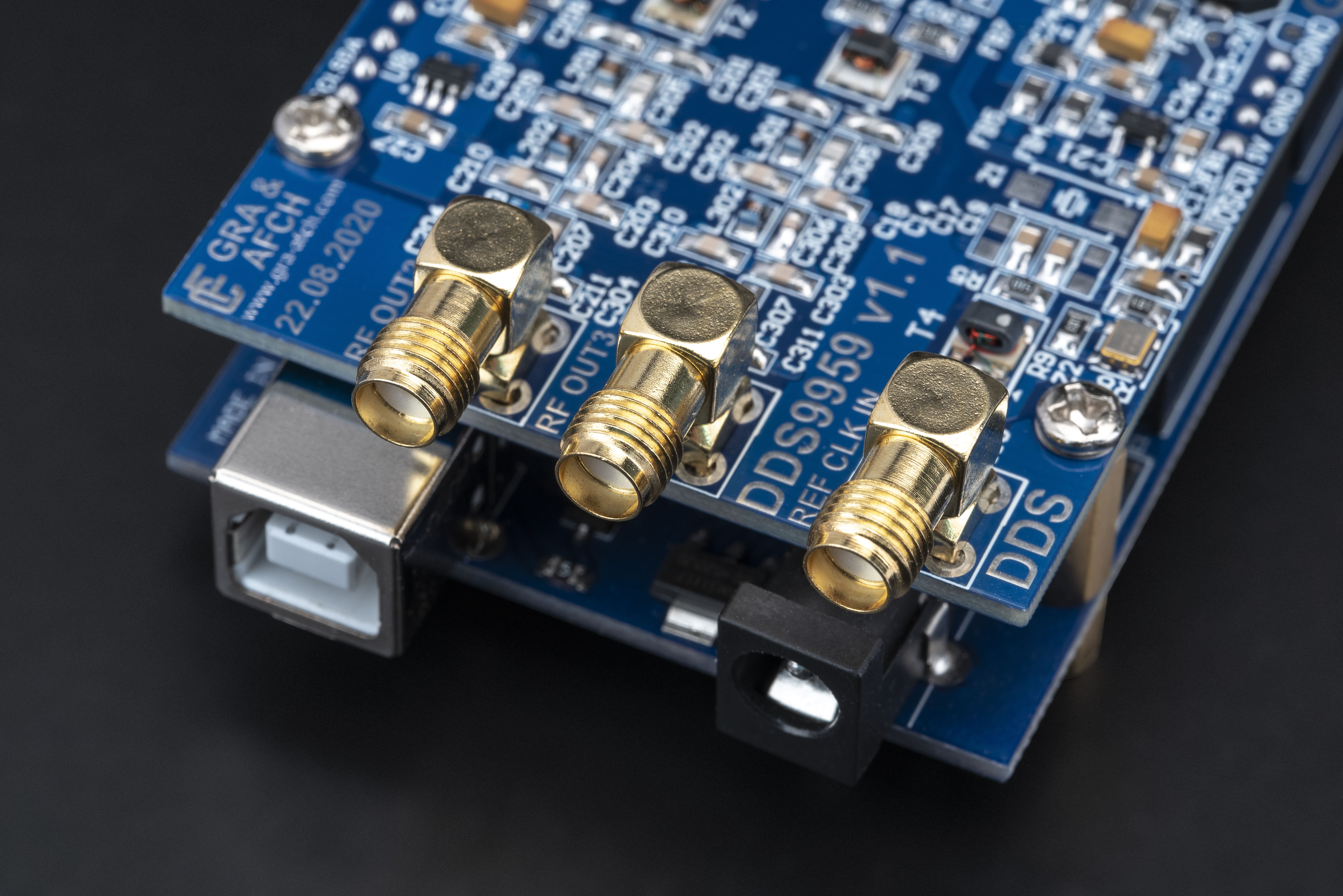
- REF CLK IN – external reference clock input, up to 600 MHz. (this source is NOT INCLUDED).
Features:
- At the output of each channel is a transformer to reduce even harmonics.
- Additionally balancing transformer is used for XO, TCXO and REF CLK IN options.
- Easy to connect OLED display.
- Device control with one encoder and one button.
- The synthesizer is capable to generate sine wave.
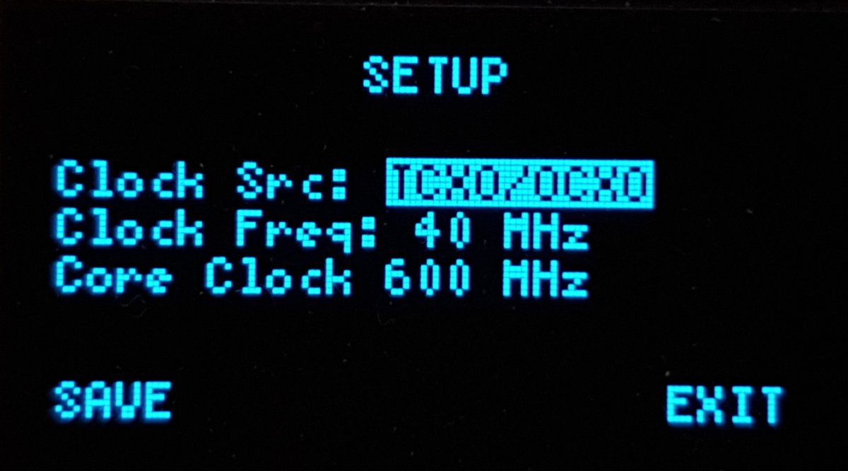
- The software allows you to select and configure the frequency of the clock generator through the user menu (without the need to recompile the program).
- Any settings can be stored in non-volatile EEPROM memory (located at Arduino Mega).
- Basic settings are applied and saved automatically.
- This shield support overclocking the AD9959 core up to 600 MHz.
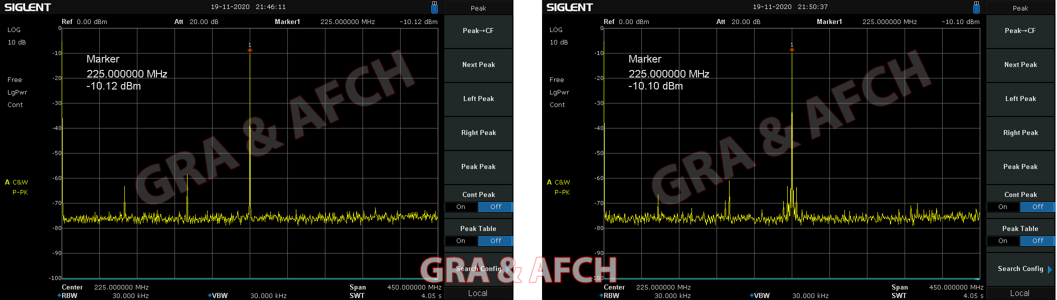
- DDS AD9959 Shield has ability to generate a signal up to 225 MHz with a core overclocking up to 600 MHz (to suppress harmonics, it is recommended to overclock the AD9959 for frequencies above 200 MHz).
Phase Noise:
This parameter is very important and interesting for those who buy DDS.
Since the intrinsic phase noise of DDS is obviously less than that of PLL generators, the final value is highly dependent on the clock source. In order to achieve the values stated in the datasheet on AD9959, when designing our DDS AD9959 Arduino Shield, we strictly adhered to all recommendations from Analog Devices: PCB layout in 4 layers, separate power supply of all 4 power lines (3.3 V digital, 3.3 V analog, 1.8 V digital, and 1.8 V analog).
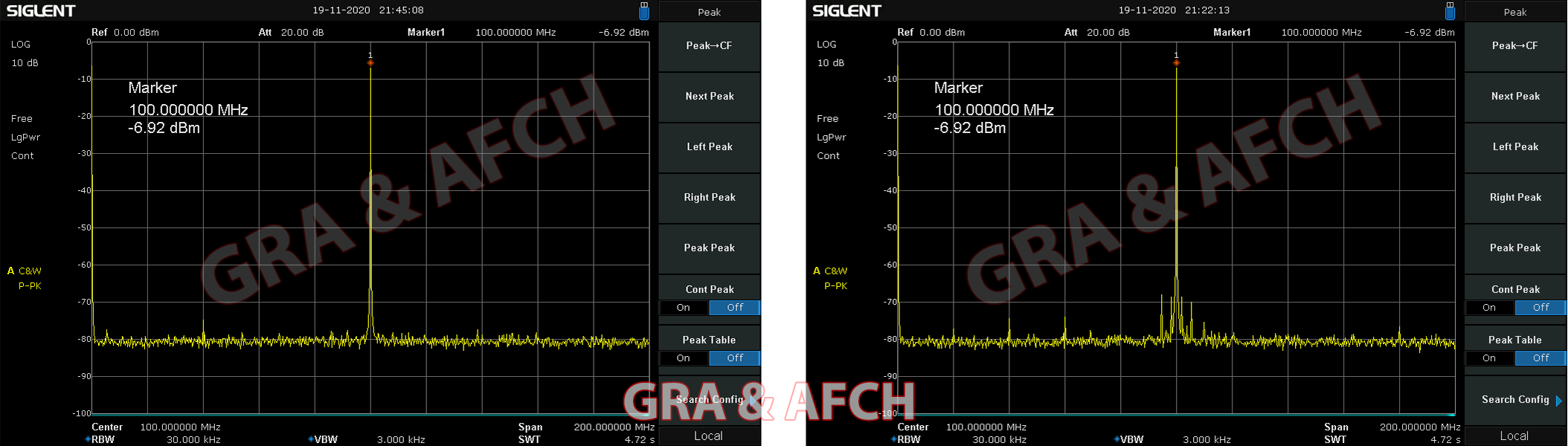
Figure below shows the phase noise level of the AD9959. Two cases are plotted: using an external 500MHz reference clock (RCLN500C) and using the built-in PLL, which multiplies the frequency of the on-board 50 MHz TCXO by 10. The output frequency in both cases is 100 MHz.
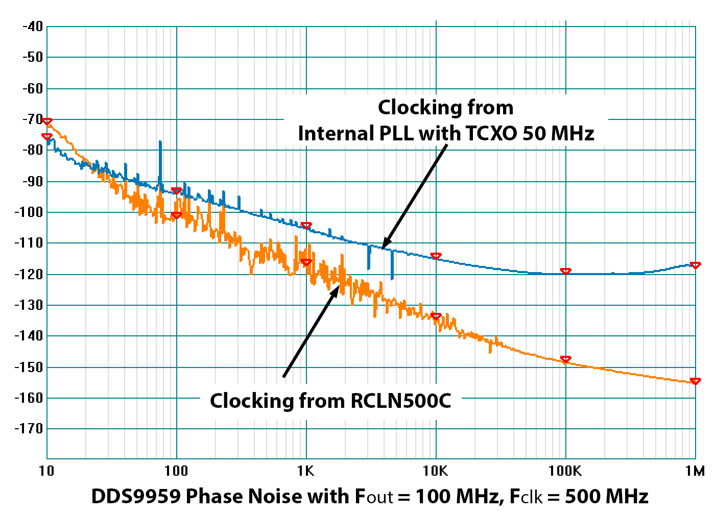
Let’s compare these two plots, for example, at a 10 kHz offset from the carrier: with the internal PLL system engaged,
the phase noise level is -115 dBc/Hz, while with the PLL system disengaged and using external clocking, the phase noise is -134 dBc/Hz.
This means that using an external clock signal results in a phase noise that is 19 dBc/Hz better (lower).
For the same output frequency, but at a 1 MHz offset from the carrier, with the internal PLL system engaged,
the phase noise level is -118 dBc/Hz, while with the PLL system disengaged and using external clocking, the phase noise is -154 dBc/Hz.
This means that using external clocking results in phase noise that is 36 dBc/Hz better (lower).
Conclusion:
When using external clock, you can get much lower phase noise than using the built-in PLL.
But do not forget that in order to achieve such results, increased requirements are put forward to the external oscillator.
For maximum performance, we recommend using our Ultra-low noise 500 MHz reference oscillator, RCLN500D-5.
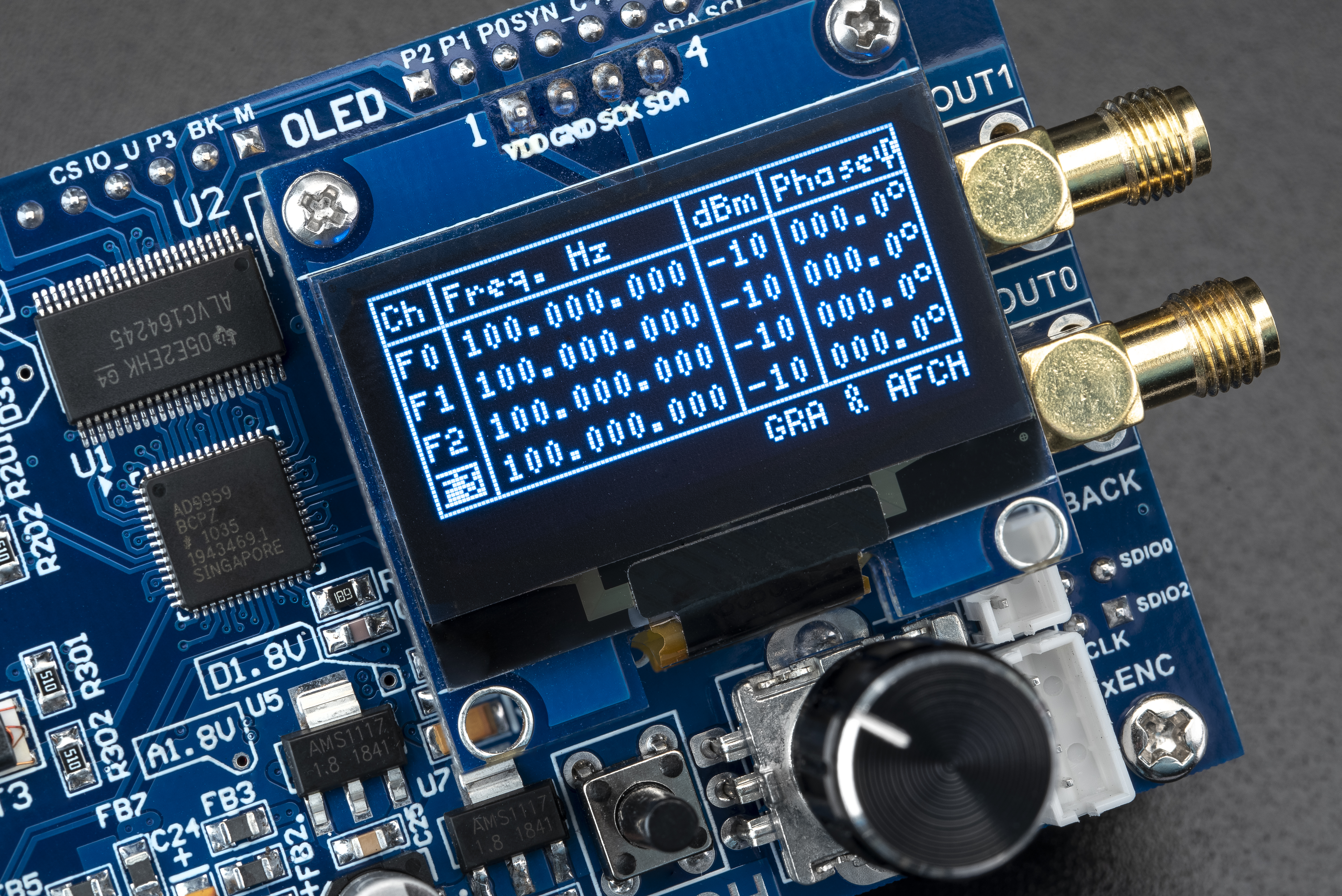
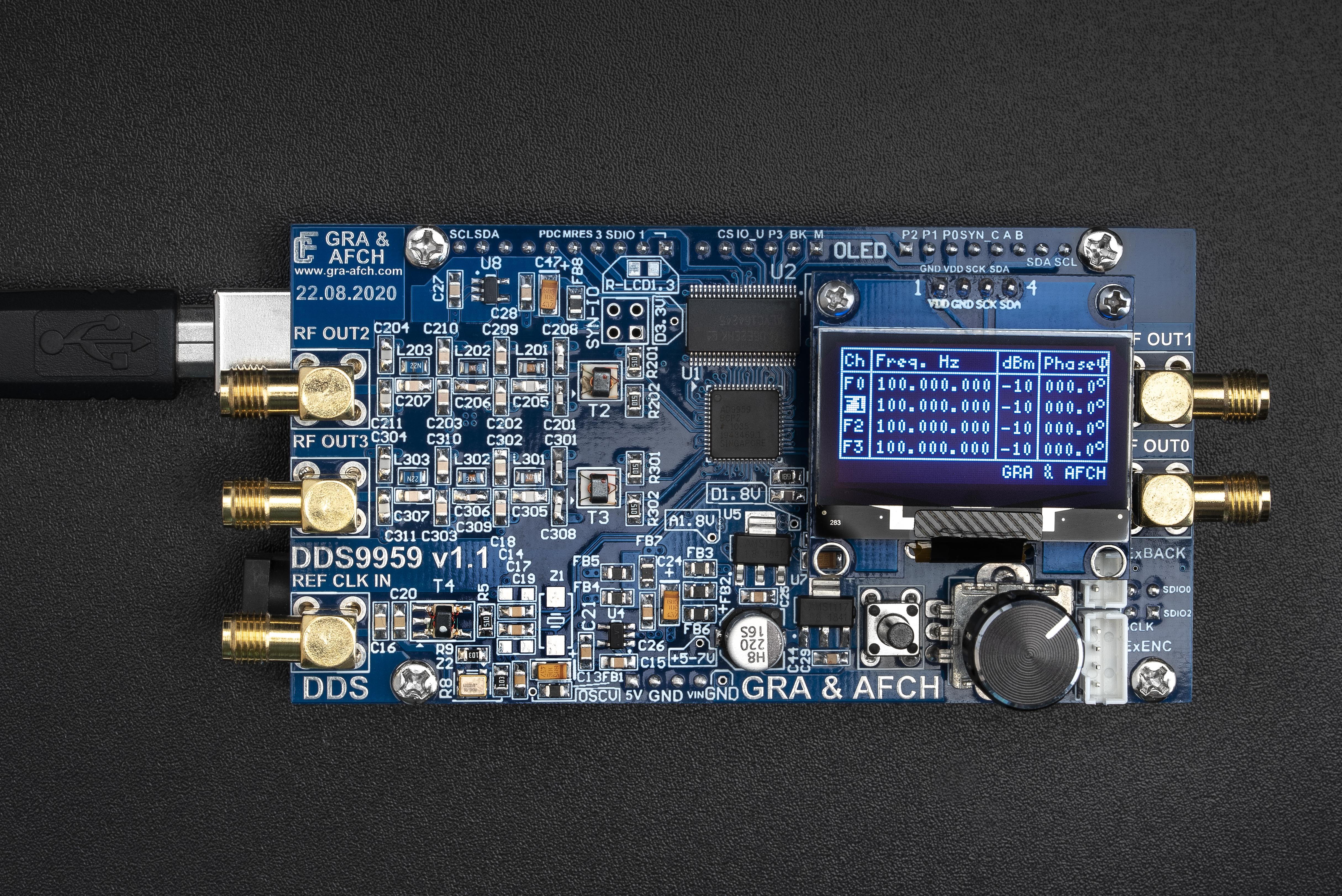
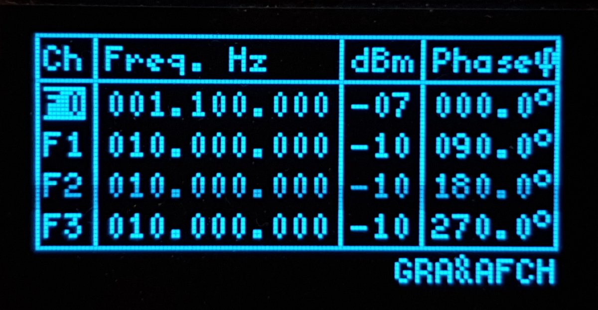
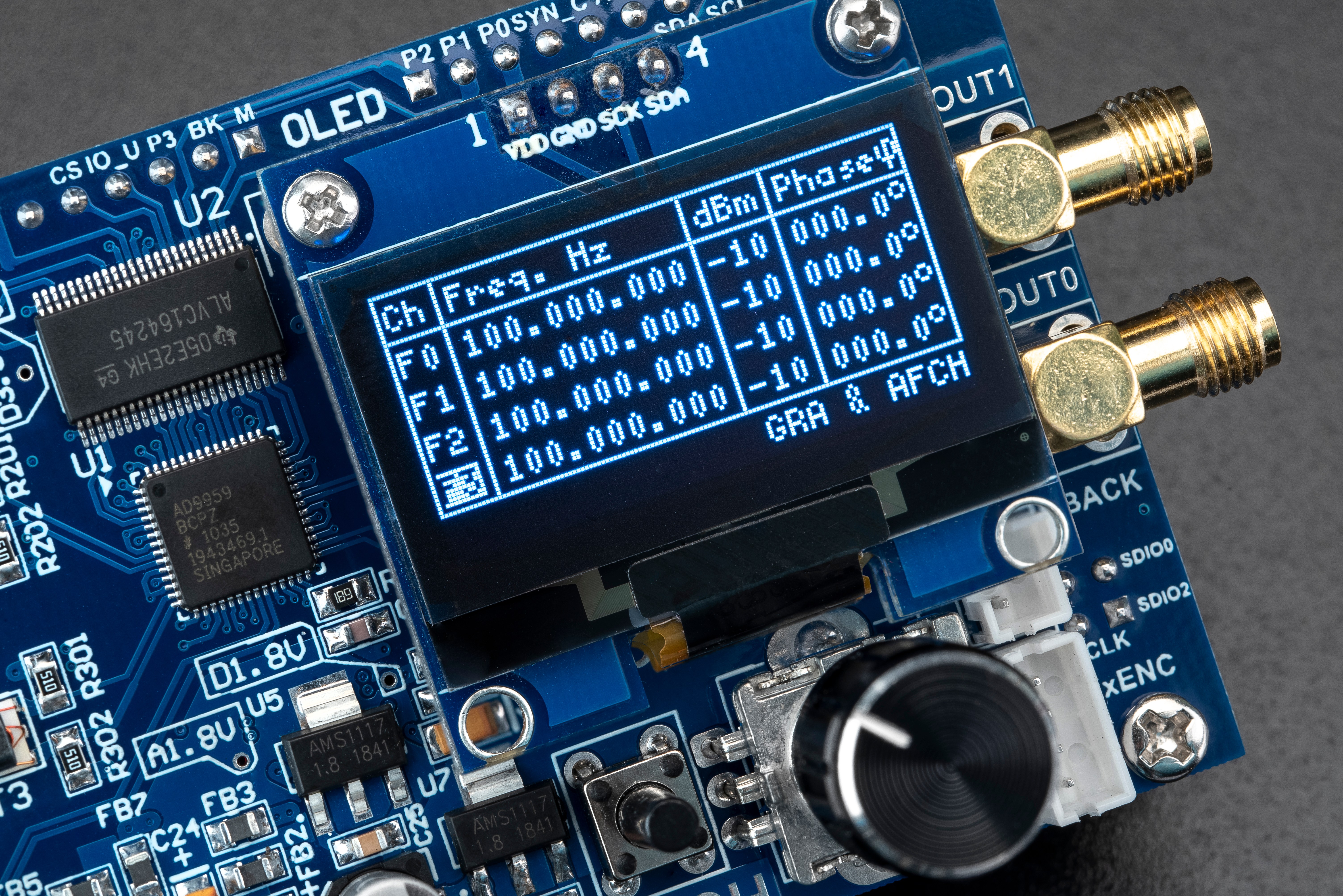
OLED Display Menus:
Dear customers!
If you have ANY questions, PLEASE ASK us.
If you have ANY questions, PLEASE ASK us.
Specifications:
| Frequency: | 4 Channels 100 kHz – 225 MHz (@600 MHz Core Clock) in 1 Hz step |
| Spurs max: | -60 dBc |
| Frequency step: | 1 Hz |
| Output power: | -3 dBm to -60 dBm (on 50 Ohm load) |
| Output level up to: | 0.448 Vpeak-to-peak (at -3 dBm) |
| Power Supply: | USB or External Power Supply 5 – 7V DC 1A |
| Output filter: | LPF 7-th order |
| Phase range: | 0 to 360 Degrees in 0.1 Degree Step |
| Reference clock sources (on choice): | XO-Crystal Oscillator, TCXO 1ppm Oscillator, or External Oscillator up to 600 MHz |
| Size: | 53.26 x 102mm |
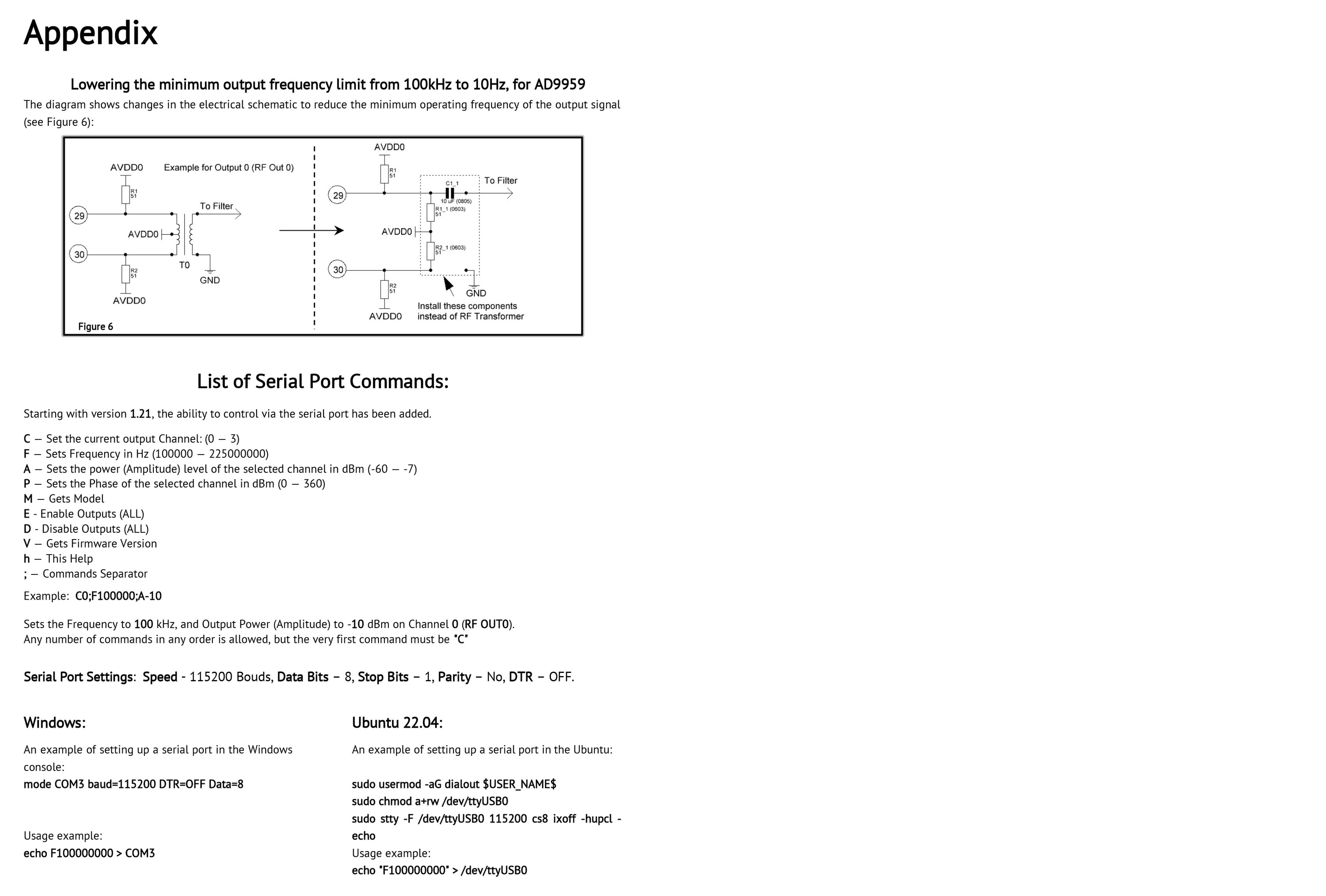
Serial Port Commands:
List of Serial Port Commands:
Starting with version 1.02, the ability to control via the serial port has been added.
C — Set the current output Channel: (0 — 3)
F — Sets Frequency in Hz (100000 — 225000000)
A — Sets the power (Amplitude) level of the selected channel in dBm (-60 — -7)
P — Sets the Phase of the selected channel in dBm (0 — 360)
M — Gets Model
E — Enable Outputs (ALL)
D — Disable Outputs (ALL)
V — Gets Firmware Version
h — This Help
; — Commands Separator
Example:
C0;F100000;A-10
Sets the Frequency to 100 kHz, and Output Power (Amplitude) to -10 dBm on Channel 0 (RF OUT0).
Any number of commands in any order is allowed, but the very first command must be “C”
Serial Port Settings:
Speed – 115200 Bouds
Data Bits – 8
Stop Bits – 1
Parity – No
DTR – OFF
Windows:
An example of setting up a serial port in the Windows console:
mode COM3 baud=115200 DTR=OFF Data=8
Usage example:
echo F100000000 > COM3
Ubuntu 22.04:
An example of setting up a serial port in the Ubuntu:
sudo usermod -aG dialout $USER_NAME$
sudo chmod a+rw /dev/ttyUSB0
sudo stty -F /dev/ttyUSB0 115200 cs8 ixoff -hupcl -echo
Usage example:
echo “F100000000” > /dev/ttyUSB0
DDS AD9959 Arduino Shield Spectrograms:
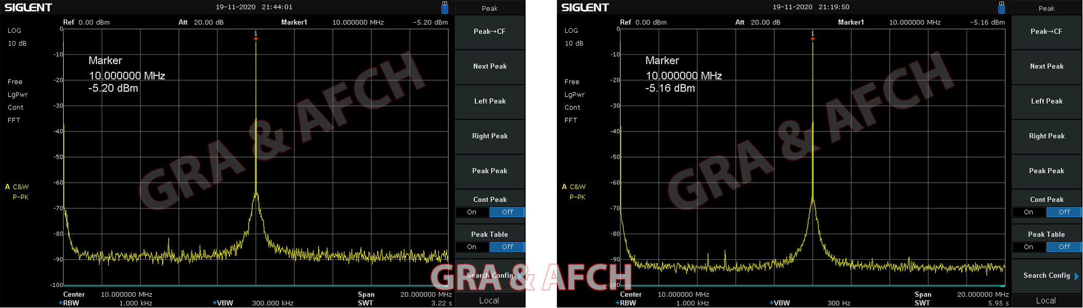
GRA & AFCH DDS AD9959 Shield External Clock Source VS Internal Clock Source Comparison:

GRA & AFCH DDS AD9959 Shield Oscillogram:
Arduino MEGA to Shield AD9959 Pinout Scheme:
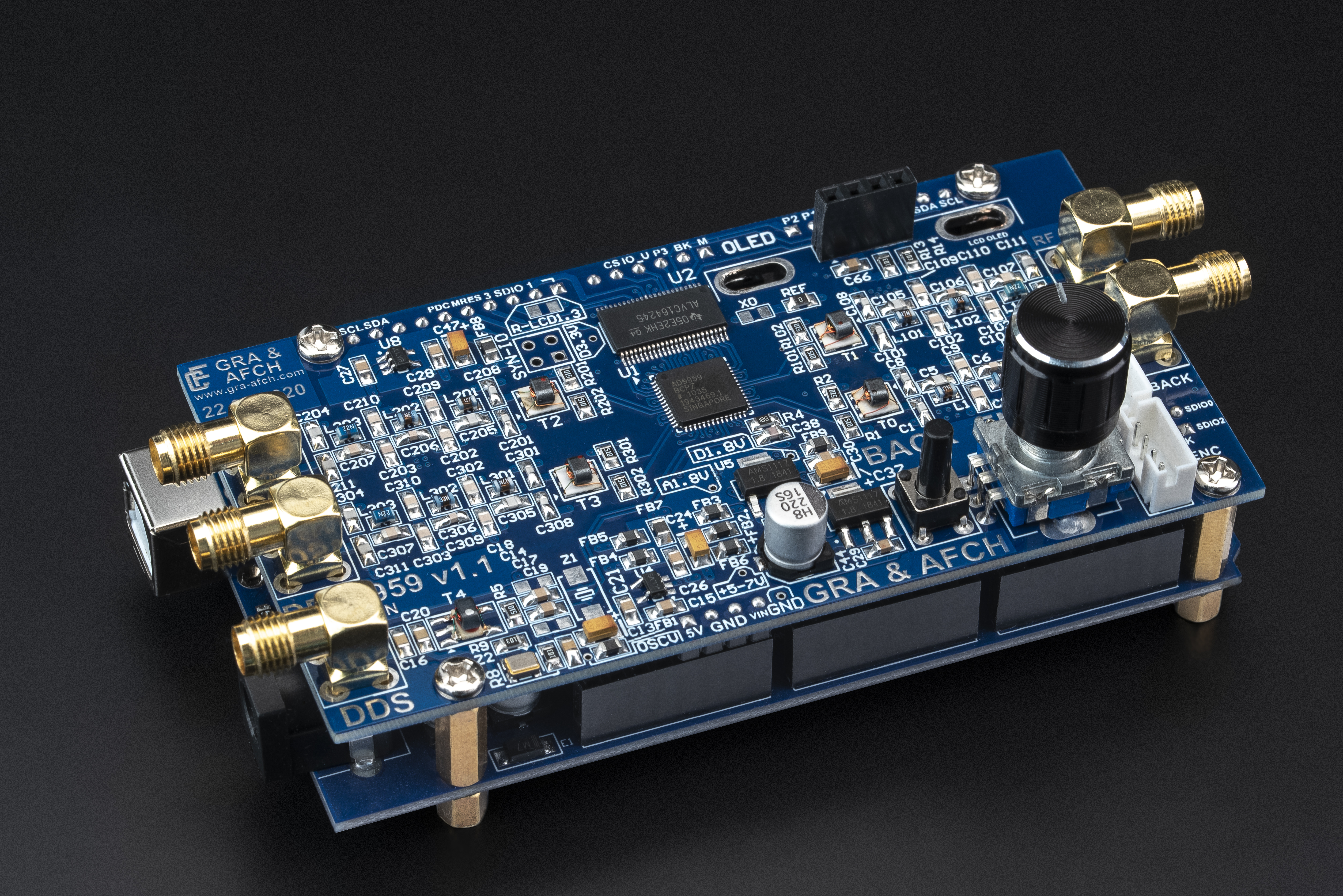
DDS Arduino Shield AD9959 RF Signal Generator Overview:
DDS Arduino Shield AD9959 RF Signal Generator:


Operating Manual
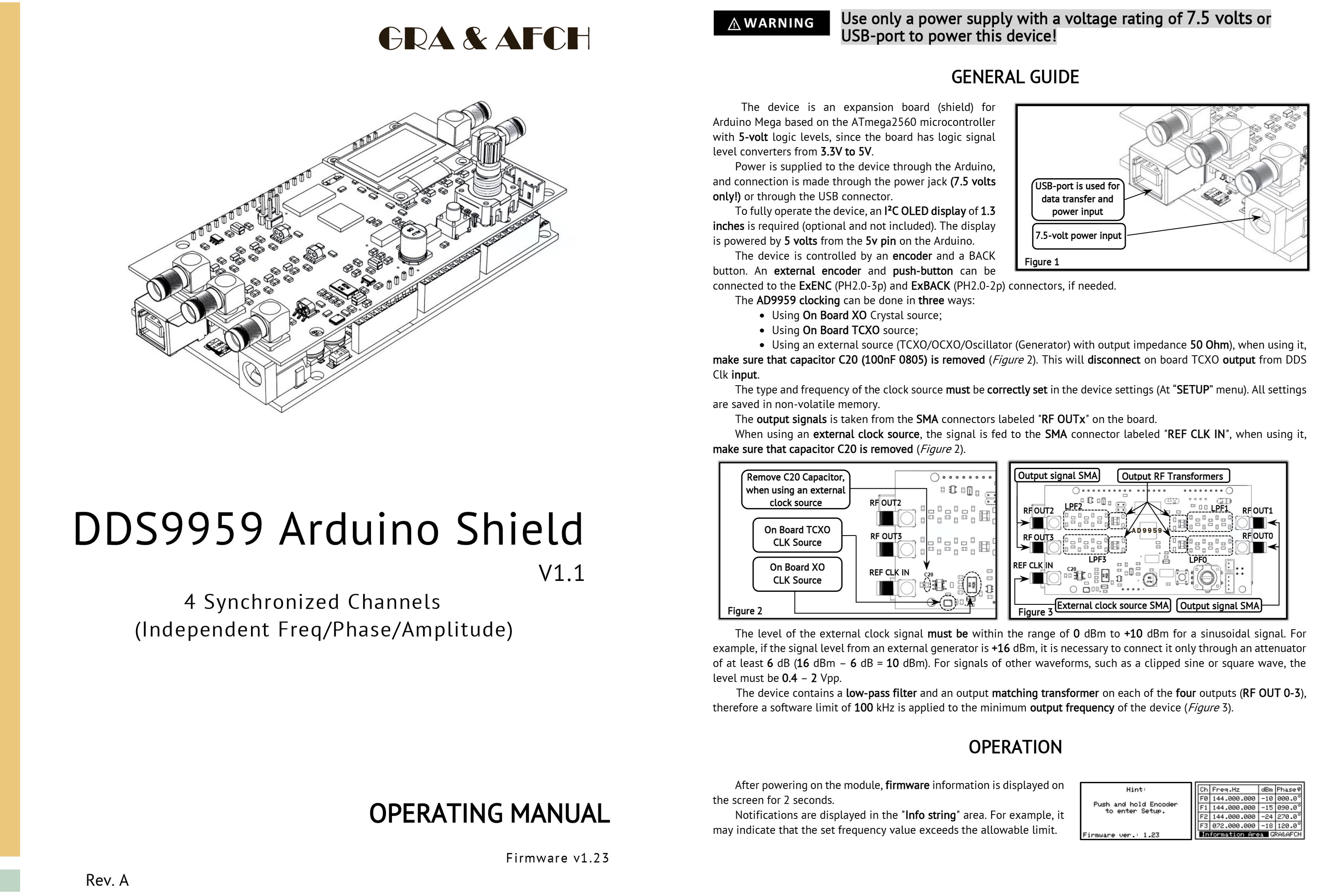

Connection Diagram

Dear customers!
If you have ANY questions, PLEASE ASK us.
If you have ANY questions, PLEASE ASK us.
Shipping and Return information
All Items are shipped from Ukraine
Via International registered Airmail
Shipments are made within 1 business day
After the payments are received and verified
It takes about 4-7 days via UPS Express delivery
It takes about 10-18 days via Standard shipping
It takes about 35-45 days via Economy shipping
We combine multiple Items to save on shipping
UPS Express Shipping time (recommended):
| Europe: | 3-5 days |
| Germany: | 3-5 days |
| USA, Canada: | 4-7 days |
| Asia, South America: | 5-7 days |
| Australia, New Zealand: | 5-7 days |
| Africa, Central America: | 5-7 days |
Standard Shipping time:
| Europe: | 10-12 days |
| Germany: | 10-12 days |
| USA, Canada: | 10-15 days |
| Asia, South America: | 10-18 days |
| Australia, New Zealand: | 12-18 days |
| Africa, Central America: | 12-18 days |
Economy Shipping time:
| Europe: | 25-30 days |
| Germany: | 25-30 days |
| USA, Canada: | 30-35 days |
| Asia, South America: | 35-45 days |
| Australia, New Zealand: | 45-55 days |
| Africa, Central America: | 45-55 days |
Return Policy
All Returns are accepted
- For Return you should contact Us within 14 Days after receiving the Item
- Refunds are made as Money back or Replacements (buyer’s choice)
- Return Shipments are paid by the buyer
- No restocking fees are charged
Customs Policy
We as a seller do not receive from the buyer any charges any sales taxes and handling fees.
In any case we are not responsible for Tax(VAT) or any other Import duties or any other equivalent fees that arises upon delivery.
Please consult with your local Customs legislation and visit your local Customs department or website before making any purchases.
Downloads
Shield AD9959 Series Firmware repository: AD9959 Shield RF Unit
Arduino Drivers repository: Shield DDS AD RF Units USB drivers
DDS9959 3D Model (Step):
DDS9959 v2.3 3D Model (Step) (23 downloads)
You may also like…
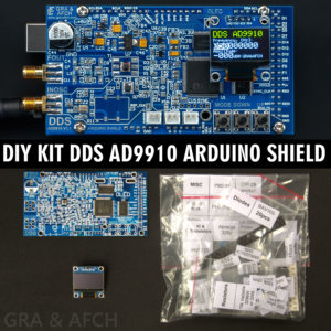
DIY KIT for DDS AD9910 Shield for Arduino RF Signal Generator AM/FM/SWEEP [600 MHz, @1.5 GHz Core Clock, Low Spurs, Low Harmonic]
DIY KIT for DDS (Direct Digital Synthesis) Analog Devices AD9910 Arduino Shield
Easy connection to Arduino MEGA 2560 without additional wires and converters
For maximum performance we recommend Ultra-low noise reference oscillator RCLN1000
All functions of the DDS AD9910 are brought to the contacts of the Arduino MEGA
With this you can fully reveal all the capabilities of the DDS AD9910 Shield
PCB Design Schematics Case and Software made by GRA & AFCH$199.95 – $279.95 Select options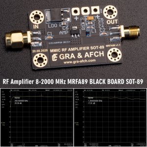
RF Amplifier 8-2000 MHz, GAIN = 20 dB, P = +20 dBm MMIC MRFA89 SOT-89 [GOLD PLATED]
MRFA89 RF Amplifier
The board has RF MMIC Amplifier in SOT-89 package (TQP369185 by defaults)
Our MRFA89 RF Amplifier also includes input/output DC blocking capacitor,
RF choke, bypass capacitors and 5V regulators in DPAK package.
SMA connectors used for input/output.
Size of the PCB 45x30mm, FR-4 material, double-sided with solid plated ground plane on the back.$19.95 Add to cart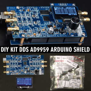
DIY KIT for DDS AD9959 Arduino Shield RF Signal Generator 4 Synchronized DDS Channels [225MHz, @600 MHz Core Clock, Low Spurs, Low Harmonic]
DIY KIT for DDS (Direct Digital Synthesis) Analog Devices AD9959 4 Synchronized DDS Channels
Arduino Shield Easy connection to Arduino MEGA 2560 without additional wires and converters
All functions of the DDS AD9959 are brought to the contacts of the Arduino MEGA
With this you can fully reveal all the capabilities of the DDS AD9959 Shield
PCB, Design, Schematics, Case and Software made by GRA & AFCH$219.95 – $299.95 Select options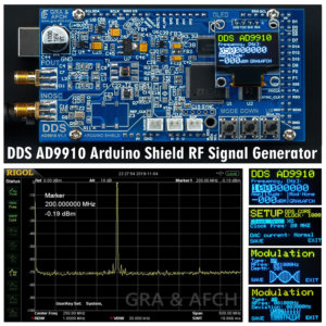
DDS AD9910 v2 Shield for Arduino RF Signal Generator AM/FM/SWEEP [600 MHz, @1.5 GHz Core Clock, Low Spurs, Low Harmonic]
DDS (Direct Digital Synthesis) Analog Devices AD9910 Shield for Arduino
This device is designed to ensure seamless integration with Arduino MEGA 2560
It does not require any extra wires or converters to work properly
For maximum performance we recommend Ultra-low noise reference oscillator RCLN1000
All functions of the DDS AD9910 are brought to the contacts from the Arduino MEGA
With this you can fully reveal all the capabilities of the DDS AD9910 Shield
PCB Design Schematics Case and Software made by GRA & AFCH$209.95 – $289.95 Select options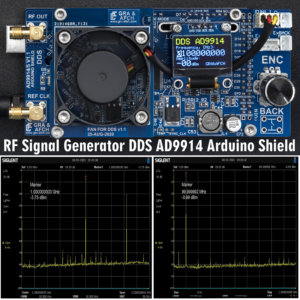
DDS AD9914 Arduino Shield RF Signal Generator [1.4GHz @3.5GHz Core Clock, Low Spurs, Low Harmonic]
DDS (Direct Digital Synthesis) Analog Devices AD9914
Arduino Shield Easy connection to Arduino MEGA 2560 without additional wires and converters
All functions of the DDS AD9914 are brought to the contacts of the Arduino MEGA
With this you can fully reveal all the capabilities of the DDS AD9914 Shield
PCB, Design, Schematics, Case and Software made by GRA & AFCH$699.95 – $904.95 Select options
DDS AD9915 Arduino Shield RF Signal Generator [1GHz @3GHz Core Clock, Low Spurs, Low Harmonic]
DDS (Direct Digital Synthesis) Analog Devices AD9915
Arduino Shield Easy connection to Arduino MEGA 2560 without additional wires and converters
All functions of the DDS AD9915 are brought to the contacts of the Arduino MEGA
With this you can fully reveal all the capabilities of the DDS AD9915 Shield
PCB, Design, Schematics, Case and Software made by GRA & AFCH$599.95 – $679.95 Select optionsAccessories